
- Каталог оборудования Siemens
- Каталог продуктов Siemens Industry
- Приводная техника
- Техника автоматизации
- Системы автоматизации
- Системы визуализации SIMATIC HMI
- Системы идентификации
- Промышленные коммуникации SIMATIC NET
- Промышленные аппараты управления SIRIUS
- Промышленные информационные технологии
- Управление на базе РС
- Системы управления процессом
- Контрольно-измерительные приборы
- Измерительные преобразователи для давления
- Приборы измерения температуры SITRANS T
- Расходомеры
- Введение
- SITRANS F M электромагнитные расходомеры
- SITRANS F C - кориолисов массовый расходомер
- SITRANS F US - ультразвуковой расходомер
- Врезные ультразвуковые расходомеры
- Общая информация и руководство по подбору
- SITRANS FUS060 преобразователь сигнала
- SITRANS FUS080 преобразователь сигнала
- SONOFLO SONO 3300 Industry ультразвуковой расходомер
- SONOFLO SONO 3100 ультразвуковой расходомер
- SONOFLO SONOKIT ультразвуковой расходомер для монтажа на существующем трубопроводе
- SITRANS FU380
- SITRANS FUS380
- Energy calculator SITRANS FUE950Pt500 temperature sensor pairs
- Energy calculator SITRANS FUE950
- Накладные ультразвуковые расходомеры
- Sonic Clamp-on ultrasonic flowmeters
- Врезные ультразвуковые расходомеры
- SITRANS F X (Vortex)
- SITRANS F O delta p primary differential pressure devices
- SITRANS F R rotary-piston meters
- SITRANS F RA110 electric flow registers
- Pulsers with inductive pick-up
- Уровнемеры
- Позиционеры
- Устройство для защиты и пуска двигателей SIMOCODE-DP
- Сигнализаторы сбоев в промышленном процессе
- Аппаратные ПИД-регуляторы SIPART
- Встраиваемые самописцы и индикаторы
- Технологии взвешивания
- Дополнительные компоненты
- Коммуникации и программное обеспечение
- Directives
- Анализаторы процесса
- Блоки питания SITOP
- Продукты для специальных требований
- Energy
- Автоматизация и безопасность зданий
- Низковольтная коммутационная техника
- Технология безопасности
- Системные решения и продукты для отраслей
- Сервис

Energy calculator SITRANS FUE950
- Заказные данные (1)
- Аксессуары (34)
- Информационные материалы
Информационные материалы
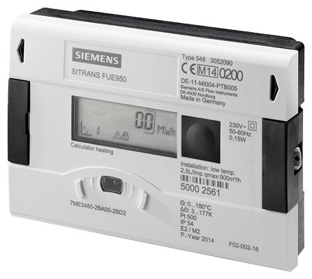
SITRANS FUE950 is a universal thermal energy calculator, which meets the requirements EN 1434 and has the MID and PTB K7.2 approval for energy metering with the media water.
SITRANS FUE950 has been developed for the SITRANS FUS380/FUE380 and alternatively MAG 5000/6000 or FST020. SITRANS FUE950 is modular in construction and can by order be fitted with optional modules depending on the application. The FUE950 supports none of the SITRANS FX, FC products and only some of the FUS clamp-on products.
Область применения
The SITRANS FUE950 is able to handle 3 kinds of applications, means energy calculation in:
- District heating applications
- Chilled water applications
- Combined cooling/heating applications
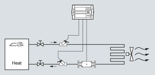
Energy metering in heating, hot water applications (code "A" and "B")
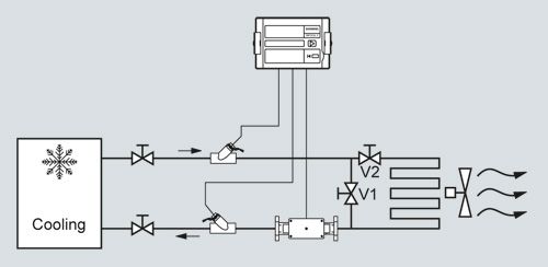
Energy metering in cooling, chilled water applications (code "C" and "D")
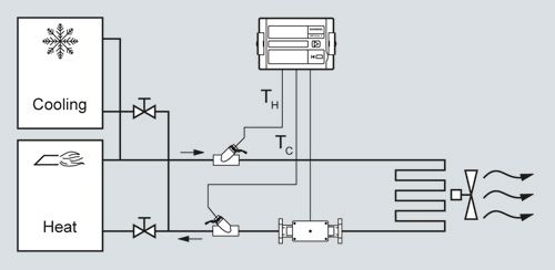
Energy metering in combined cooling/heating applications (code "E" and "F")
Дизайн
SITRANS FUE950 has an easy-read 8-digit LCD display with associated pictograms for the various functions. As the display has been made for several applications, some figures/symbols not used for normal district heating applications will be shown.
SITRANS FUE950 has a push button for simple operation and provides user-friendly control via the various display menu loops. The display will always be configured for the application chosen, and for the selected display settings.
The integrator has an IP54 plastic housing and is designed for wall or panel mounting. The housing comes with prepared rubber gaskets cable entries for fast and easy installation.
Operation menu loop structure
The FUE950 display has six menu loops and the menus are numbered in the display from 1 to 6. Some display menus consist of two values (to maximum seven) that are shown alternately at 4-second intervals.
The main menu loop no. 1 with the current data, e.g. for energy, volume, flow rate and temperature, is preprogrammed as default setting.
In the combined heating/cooling configuration the menu loop no. 5 (tariff menu loop) will be activated additionally.
Displays and output pulses
Units: MWh, GJ, Gcal, MBtu, m3, gal, m3/h, GPM, °C, °F and kW; all decimal points are statically (the unit "gal" is shown with factor x 100).
The display unit and the last fractional digit are typical used for the pulse outputs.
Функции
Technical principle
Calculation of energy is based on the following formula:
Energy = Volume x (THot - TCold) x Kfactor (Ti)
Volume: Volume [m3] of a given amount of volume pulses
THot: Measured temperature in the hot line
TCold: Measured temperature in the cold line
Kfactor (Ti): Thermal coefficient of media enthalpy and heat content
The energy calculation is made by a counter and depends on temperature difference, pulse input frequency and legal requirements.
The calculator always carries out at least one energy calculation every 2 seconds. If the connected flowmeter has not sent enough pulses the energy calculation and flow indication is also based on the 8 seconds value.
Data memory
The FUE950 has a history memory of 24 periods (months, weeks, days). The following values are stored monthly, weekly or daily in the EEPROM on the programmed day of 1…31 (via software tool).
- Date/Time
- Volume
- Energy
- Error day counter
- Tariff energy 1
- Maximum monthly flow rate
- Tariff energy 2
- Maximum monthly power
- Tariff definition 1
- Date of maximum monthly flow rate
- Tariff definition 2
- Date of maximum monthly power
- Pulse counter input 1
- Pulse counter input 2
- Operation hours
Data logger memory (LOG)
The LOG of the calculator is stored every 24 hours with all cumulative values in the EEPROM. The storage frequency can be selected from various storage intervals (5, 6, 10, 12, 15, 20, 30, 60 minutes or the default setting of 24 hours). The data which are stored in the LOG could be read out using a software tool and can be used for evaluations.
Extract of possible LOG settings
Storage interval
Values
Number of data records
Recording period
5 minutes
- Error status
- Overload time temperature
- Overload time flow rate
- Forward temperature
- Return temperature
- Date and time
- Energy
- Tariff energy 1
- Tariff energy 2
- Tariff definition 1
- Tariff definition 2
- Volume
- Error day counter
440
36.6 hours
15 minutes
440
110 hours
1 hour
440
18.3 days
24 hours
(default setting)440
440 days
Maximal Values
The integrator creates max. values for power and flow rate based on consumption time, which are stored in the EEPROM. The integration intervals are adjustable to 6, 15, 30 or 60 minutes and 24 h. Default setting is 60 minutes.
Tariff/Accounting date function
The calculator includes two independent memories in which the accumulated energy at two programmable tariff dates are stored.
- Last accounting date
- Last but one accounting date
Values stored
- Energy
- Volume
- Tariff counter 1
- Tariff counter 2
- Pulse counter 1
- Pulse counter 2
- Date
The integrator offers two optional tariff memories for monitoring plant load states. Here it concerns threshold value tariffs. Extensive tariff conditions make it possible to adapt the calculator individually to the required customer-specific applications.
Both tariffs are separately configurable and independent from each other. Energy or time can be measured alternatively per tariff register dependent on the tariff mode adjusted in each case.
With the "time triggered tariff function" the switch-on time and the switch-off time are adjustable independent from each other for each day of the week in steps of 15 minutes.
The following tariff limit types of the tariff are possible:
(This example applies to the display at 3 fractional digits after comma)Type
Description
Limit
Limit resolution
dT
Temperature difference
1 … 190 °C
1 °C
-dT
Negative temperature difference
1 … 190 °C
1 °C
TR
Return temperature (low)
1 … 190 °C
1 °C
TV
Forward temperature (high)
1 … 190 °C
1 °C
P
Power
10 … 2500 kW
10 kW
Q
Flow
1 … 255 m3/h
1 m3/h
FE
"Theoretically forward energy" with return temperature of 0 °C
Z
"Time triggered" counting energy
E
"External" counting energy
Error handling and memory
Events such as changes and faults are stored in a non-volatile memory with a capacity of up to 127 entries. The following events are recorded:
- Checksum error
- Temperature measurement error
- Error hours
- Start and end of test mode
If SITRANS FUE950 records an error, this will be automatically indicated by a "alarm symbol" on the display.
To protect the reading data, all the relevant data are saved in a non-volatile memory (EEPROM). This memory saves the measured values, device parameters and types of error at regular intervals.
The following events are recorded:
- Temperature sensor error
- Swapped hot and cold temperature sensors
- Battery low warning
- Power supply failure
- Optical communication warning
- RAM checksum error
Outputs/Inputs/Communication
Communication interfaces:
SITRANS FUE950 is fitted with an optical infra-red send/receive port in accordance with EN 1434/IEC 61107, protocol standard, EN 1434/EN 60870-3 (M-Bus protocol).
A specific optical head with a permanent magnet (IrDA-adapter) in accordance with EN 1434 can be used for readout data or communication with the parameterization software.
2 ports for optionally plug-in modules
The calculator features 2 ports for the plug-in modules.
One slot is for the function modules and the other for the communication modules.
Communication modules
The following communication modules are available as options: RS 232 module, RS 485 module and M-Bus module. The RS 232 and RS 485 communication modules are serial interfaces and permit data exchange with the calculator. For this purpose a special data cable is necessary.
The M-Bus module is a serial interface for communication with external devices (M-Bus Master/Centre). According to the M-Bus structure a number of calculators can be connected to a control centre.
Pulse input module
Two pulse inputs are available. The pulse value and the unit is configurable for energy, water, gas or electrical meter by parameterization software. Data are separate cumulated in different registers and are also stored on the two accounting day's (Tariff registers).
Combined pulse Input/Output module
Two pulse inputs combined with one pulse output are available on one module. The pulse inputs are configurable with value and the unit by parameterization software.
The pulse output is also programmable using the parameterization software.
Pulse output
The calculator provides levels for two optional external pulse outputs, which can be freely programmed using the parameterization software tool.
Default setting is one pulse which occurs per change in the least significant digit in the display with the unit and resolution selected by the device ordering.
Possible pulse output values
- Energy (default setting)
- Volume (default setting)
- Tariff energy 1
- Tariff energy 2
- Tariff condition 1, limit switch
- Tariff condition 2, limit switch
- Energy error
- Volume error
- Volume with specific resolution (0.1, 1.0, 10 or 100)
- Energy with specific resolution (0.1, 1.0, 10 or 100)
Combined current output module
Optional module with 2 passive 4 ... 20 mA outputs.
Possible output values:
- Power (default setting for output #1)
- Flow (default setting for output #2)
- Hot, cold or difference temperature
The settings can be configured by parameterization software. The current output module occupies both ports, means no other plug-in module will possible to plug in.
Module combinations
The calculator has a group of extension modules for communication and another group of extension modules for additional functionality. These modules are available first selected within the calculator, or for retrofitting in the field.
One single function module as well as one single communication module out of following modules is selectable.
Function modules:
- Pulse input module, 2 inputs
- Pulse output module, 2 outputs
- Combined pulse module 2 inputs, 1 output
- Combined current output module, 2 x passive 4 ... 20 mA
(occupies both ports)
Communication modules:
- M-Bus (M-Bus protocol according EN 1434-3)
- RS 232 (M-Bus protocol according EN 1434-3)
- RS 485 (M-Bus protocol according EN 1434-3)
Интеграция
SITRANS FUE950 is a multi-purpose energy calculator for media water which meets the requirements of EN 1434. Further, the energy calculator has been specially developed to process volume pulses from SITRANS FUS380/FUE380 or alternatively MAG 5000/6000 or FST020 transmitter.
Чертеж

SITRANS FUE950, dimensions in mm (inch)
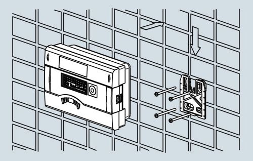
Wall mounting

Panel mounting, dimensions in mm (inch)
Особенности
Basic functions
- Prepared for heating, cooling measurement
- Approval for MID for heat metering and PTB K7.2 for cooling
- High-accuracy thermal energy metering, meets EN 1434 requirements
- Measured temperature range -20 … +190 °C (-4 … +374 °F)
- Instantaneous values for energy/volume flow
- Battery or mains powered
- Battery version with battery lifetime of typically up to 10 years
- Optical data interface
- Real date and time
- Auto-detection of 2-wire or 4-wire temperature sensors
Additional functions
- Individual tariff functions
- Advanced functions for cooling/heating applications or the combination
- Memory for 24 periods (months, weeks, days)
- Data logger function
- Expandable functionality with 2 optional plug and play add-on modules
- Communication over M-Bus, RS 485 or RS 232
Add-on modules
- Plug-in module with 2 extra pulse inputs
- Plug-in module with 2 pulse outputs
- Plug-in module with combination of input and output pulses
- Plug-in module for M-Bus communication
- Plug-in module for RS 232 or RS 485 communication
- Plug-in module with 2 passive current outputs (4 ... 20 mA)
Схема подключения
Electrical connection for SITRANS FUS380/FUE380/FUE950 and MAG 5000/6000/FUE950
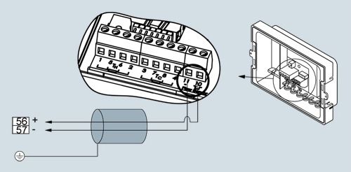
The diagram shows the connection between SITRANS FUE950 (terminals 10 and 11) and FUS380/FUE380 and MAG 5000/6000 (terminals 56 and 57). Temperature sensors must be connected to terminals 5 (1) and 6 (2) (TH) and 7 (3) and 8 (4) (TC).
Note:
The right flowmeter pulse output value must be equal to the FUE950 pulse input value and must be checked via the user menu of the transmitter MAG 5000/6000 or nameplate of FUE380 or FUS380.Технические данные
Approval
MID approved in accordance with energy meter EN 1434 and PTB K7.2 (German national cooling approval)
Approved temperature range
- Heating
0 … 180 °C (32 … 356 °F)
- Cooling
0 … 105 °C (32 … 221 °F)
Absolute temperature range
-20 … +190 °C (-4 … -374 °F)
Differential temperature
- Heating
3 … 177 K (starting at 0.1 K)
- Cooling
3 … 102 K
Measuring accuracy
Meets requirements of EN 1434
Typically max. ± (0.5 + 3 K/Δθ) [%] of measured valueMeasuring rates
- Battery type D-cell
Volume: 1 s, temperature: 4 s
- Mains versions
Volume: 1/8 s, temperature: 2 s
Flow range
Depends on pulse input value (IN0), see “Selection and Ordering data”
Power range value
Depends on pulse input value as follows:
Pulste input value (I/P or gal/P)
Max power [kW]
1
15000
2.5
15000
5
15000
10
150000
25
150000
50
150000
100
1500000
250 *)
1500000
500 *)
1500000
1000 *)
15000000
*) not available for gal/pulse
Typical accuracy of FUE950

User interface (always included)
Display
8-digit LCD display with associated pictograms/symbols
Units
MWh, GJ, Gcal, MBtu, m3, m3/h, GPM, gal, °C, °F, kW, MBtu/h (gal is shown with factor x 100)
Totalizer value range
99 999 999 or 9 999 999.9 (0 and 1 digit after comma). Display digits: Flow in 6 digits; Volume, power and energy in 8 digits
Values
Power, energy, volume, flow rate, temperatures
Push button
Single push button for the menu controlling
Optical interface IrDA interface
ZVEI optical interface with M-Bus protocol as per EN 1434, connection via separate IrDA-adapter
baud rate: 300 or 2400Rated operation conditions
Enclosure
IP54 in accordance with IEC 529
Material
- Housing
C Lexan 141R (or similar); colors: light gray (top part) and black (bottom part)
- Pipe/wall fitting
PA 6,6 GF25 (or similar)
- Other plastic parts
ABS Cycolac GPM500 (or similar)
- Gaskets
Neoprene and rubber cable bushings: EPDM 50
- Rubber cable bushings
EPDM 50
Temperature
- Ambient
5 … 55 °C (41 … 131 °F)
- Storage
-25 … +70 °C (-13 … +158 °F)
Relative ambient humidity < 93 %Environment class
- Mechanic class
M1/M2
- Electromagnetis class
E1/E2 (MID) or C (DIN EN 1434)
Temperature input (always included)
Function
The temperature sensors must be connected to terminals 1-5 and 6-2 (TH) and 3-7 and 8-4 (TC) depending on cable type (2-wire or 4-wire).
Temperature range
Absolute measuring range-20 … 190 °C (-4 … 374 °F) for TH and TC
Temperature difference
Start 0.1 K, min. 3 K, max. 177 K
Measurement cut-off
0.125 K
Display resolution
TH and TC: 0.1 K
ΔT: 0.1 K
16-bit digital resolution AD converterSensor types
Pt100 or Pt500 as 2-wire or 4-wire; Standard is Pt500.
Sensor cable length: up to 10 m (according EN 1434 and MID-type approval).Sensor connection
4-wire or 2-wire; auto detection of connection version
Flow input (IN0)
(always included)Function
Used as standard for flow input of the external flowmeter. The input is marked as 10 (+ Flow Pulse),
11 (- Gnd) on the terminal strip.Note: The pulse input value selection must be the same as the pulse output setting of the flowmeter.
Pulse value
1 … 1000 l/pulse or 1 … 100 gal/pulse, selection by corresponding order code. Will be shown at the device label
Pulse frequency
≤ 100 Hz (200 Hz)
Pulse ON-time
≥ 3 ms
Pulse OFF-time
≥ 2 ms
Type
Active pulse input
Terminal voltage
3.6 V DC (supplied internally by FUE950)
Flowmeter installation place
The flowmeter installation place can be in the hot line or cold line (“forward or return pipe”) selected by corresponding order code. The “installation place” will be shown at the device display and nameplate
Connected cable
Max. 10 m (shielded cables are highly recommended)
Ports for option modules
Type
The calculator features 2 ports for optional plug-in modules.
Function modules (Port 1 or 2)
- Pulse input module, 2 inputs (In1, In2)
- Pulse output module, 2 outputs (Out1, Out2)
- Combination module of 2 inputs (In1, In2) and 1 output (Out1)
Current output module (Port 1)
2 passive 4 ... 20 mA (#1, #2) (occupies both port 1 and 2)
Communication modules (Port 1 or 2)
M-Bus, RS 232 or RS 485 (M-Bus protocol, according EN 1434-3)
Pulse output
Function
The module contains connections for 2 pulse outputs, which can be programmed as desired using a software tool. The pulse outputs are marked as standard as O1, 'gnd' and O2, 'gnd' on the terminal strip and Out1 respectively Out2 in the display.
Type
Passive "open collector" pulse output, outputs potential isolated to each other
Pulse value
Last significant digits of the display (unit/pulse), selection by corresponding order code and setting can be read via display menu, settings changeable via software tool
Pulse output 1
- Pulse frequency
≤ 4 Hz
- Pulse width
125 ms ± 10 %
- Pulse duration
125 ms ± 10 %
- Pulse break
≥ 125 ms -10 %
Pulse output 2
- Pulse frequency
≤ 100 Hz, depending on the selected pulse length
- Ratio
Pulse duration/pulse break ~ 1:1
Pulse length
5, 10, 50, 100 ms (default: 5 ms)
External voltage supply
3 … 30 V DC
Current
≤ 20 mA with a residual voltage of ≤ 0.5 V
Possible pulse output selection
- Energy (default setting for 'Out1')
- Volume (default setting for 'Out2')
- Tariff energy 1
- Tariff energy 2
- Tariff condition 1 (limit switch)
- Tariff condition 2 (limit switch)
- Energy error
- Volume error
- Volume with specific display resolution (or with factor 0,1, 10 or 100 thereof)
- Energy with specific display resolution (or factor 0.1 thereof)
Pulse input
Function
Add-on module for two additional counters. The pulse input 1 is marked as I1, 'gnd' and the input 2 as I2, 'gnd' on the terminal strip and indicated in the display as separate registers IN1 and IN2 and can also be transferred via the communication modules.
Type
Passive "open collector" pulse inputs, outputs not potential isolated to each other, data are separate cumulated in different registers and are also stored on the two accounting day's.
Pulse value
Pulse value and the unit are configurable for energy, water, gas or electrical meter by a software tool
Default: Pulse input 0.1 m3 or 1 gal (if unit 'gal' is ordered with the Z-option "L05")
Pulse frequency
≤ 8 Hz
Pulse length
≥ 10 ms
External voltage supply
3 V DC (supplied internally by FUE950)
Current
based on Ri = 2.2 MΩ
Cable length
< 10 m connection limit
Current output module
Function
The module contains connections for 2 passive current outputs, which can be programmed individually using the software tool. The outputs are marked „#1“ and „#2“ with corresponding polarity „+“ and „-“ on the terminal strip.
The module will be connected on port 1 only, but both ports are occupied by the module.
Terminal voltage
External supply: 10 … 30 V DC (passive output)
Signal range
4 … 20 mA; 4 mA = 0 value and 20 mA = default maximum values (for #1: Power in kW and for #2: Flow with the max. values and selected unit).
Defaults:
For power it is the max. selectable value x 100 000 the last digit of display (e. g. 20 mA = 10 000.0 kW (1 digit res.) or 100 000 kW (0 digit res).
For flow it is the max. selectable value x 10 000 the last digit of display (e. g. 20 mA = 1 000.0 m3/h (1 digit res.) or 10 000 m3/h (0 digit res.).
Load
Max. 800 Ω
Upper limit
Up to 20.5 mA (exceed causes the error current value)
Signal on alarm
Errors are indicated with 3.5 mA or 22.6 mA (programmable, default: 3.5 mA)
Output values
Power, flow, temperature (configuring via software tool; default: for #1: Power and for #2: Flow)
M-Bus output
Type
The optional M-Bus plug-in module is a serial interface for communication with external devices (M-Bus Repeater)
Protocol
M-Bus according EN 1434-3
Connection
The connection is not polarity-conscious and is electrically isolated, connection of 2 x max. 2.5 mm2 wires, 300 or 2400 baud (auto baud detection), current drawn: one M-Bus load.
M-Bus address:
Each port has its own primary M-Bus address (Prim1 = the last two digits of the serial number; Prim2 = 0).The secondary address is unique for each calculator and is factory-set to equal the serial number.
RS 232 output
Type
The optional module RS 232 is a serial interface for data transmission with external devices, e.g. PC; baud rate: 300 or 2400. The module contains a 3-pole terminal strip with terminals marked 62 (TX), 63 (RX) and 64 (GND). For this purpose a special data cable is necessary.
Protocol
M-Bus according EN 1434-3
Connection
The module contains a 3-pole terminal strip with terminals marked 62, 63, 64 (max. 2.5 mm2); Connected cable length: max 10 m;
For communication with a PC a special adapter cable is required (order no. A5E02611774).
RS 485 output
Function
The optional RS 485 module is a serial interface for data transmission with external devices, e.g. PC; baud rate: 2400. The module contains a 4-pole terminal strip with terminals marked D+, D-, Vcc and GND.
Protocol
M-Bus protocol according EN 1434-3
Connection
Terminals D+ and D-; electrically isolated; 2400 baud only.
An external supply of 12 V DC ± 5 V (<5 W) is needed for the module (terminals Vcc and GND). The module terminals are max. for 2.5 mm2 wires. Connected cable length: max. 10 m
Power consumption
230 V and 24 V versions
Typical current appr. 0.15 VA
3.6 V D-cell battery
Typical battery lifetime 10 years under normal conditions (no add-on modules, max. 40 °C ambient temperature)
Supply data
Internal voltage 3.6 V by the battery or plug-in power supply module
Battery, 3.6 V type (option)
3.6 V lithium D-cell, battery lifetime typically 16 years with independently powered flowmeter
230 V AC module (option)
Plug-in module for 230 V AC (195 ... 253 V AC), 50/60 Hz (incl. battery backup)
24 V AC module (option)
Plug-in module for 24 V AC (12 ... 30 V AC) (incl. battery backup)
Battery backup (option)
Only with mains supply modules by internal 3.0 V lithium battery (type CR 2032)
Displayed values, date and time are still updated, but the measuring functions have stopped, including the flow rate measurement. Communication via optional modules M-Bus, RS 485, RS 232 or optical interface is maintained, affecting the backup battery lifetime.Accessories/Software
The parameterization software based on the M-Bus is a convenient tool for handling the calculator. It runs on Windows and is used for:
- Configuration of the calculator functionality, reading out different memories, printing out calculator logs (standard).
- Expert programming of the device (advanced setup).
- Test Lab programming of the device (full setup)
Configuration of the calculator functionality, reading out different memories, printing out calculator logs. For further details please contact your local Siemens representative.
A specific optical head with a permanent magnet in (IrDA adapter with bluetooth) accordance with EN 1434 can be used for programming/altering programming of readout data, configuration data, etc. The reader head can also be used to change measuring data.
Дополнительно
Flowmeter SITRANS FUE950 operating instructions, accessories and spare parts
Operating instructions
Description
Article No.
- English
A5E003424739
This device is shipped with Safety Notes and a DVD containing further SITRANS F US literature.
All literature is available to download for free, in a range of languages, at http://www.siemens.com/processinstrumentation/documentation
Accessories
Description
Article No.
Infrared optical head (Bluetooth type) for data acquisition & programming of FUE950
A5E02611768
Bracket for SITRANS FUE950 wall mounting (20 pcs.)
A5E02611769
Cable for data acquisition via RS 232 PC/D-sub 9F/3 wire
A5E02611774
Basic version of programming software tool for FUE950
free download from internet
Expert version of programming software tool for FUE950
A5E03478951
Test Lab. version of re-programming software tool for FUE950
(Note: Before using this Test-Lab version an online training must be completed)A5E03461778
Spare parts
Description
Article No.
Add-on modules for FUE950 (only for 7ME348 versions)
Pulse input module (2 inputs)
A5E03461432
Pulse output module (2 outputs)
A5E03461436
Combined pulse in-/output module (2 inputs and 1 output)
A5E03461437
RS232 module (M-Bus protocol)
A5E03461459
RS485 module (M-Bus protocol)
A5E03461512
M-Bus output module
A5E03461516
Combined current output module, 2 x passive 4 ... 20 mA
A5E03461583
Connection set for option modules (types: Pulse, RS 232/RS 485, M-Bus, mA) (special connection cable with 2 plugs)
A5E03461585
Power supply for FUE950 (only for 7ME348 versions)
3.6 V D-cell battery for SITRANS FUE950
A5E03461708
230 V AC supply module (incl. internal fuse T50 mA L 250 V and back-up battery) for SITRANS FUE950
A5E03461717
24 V AC supply module for SITRANS FUE950, incl. back-up battery
A5E03461719
Pocket for temperature sensors Pt500 (for related 4-wire Pt500 type only, 1 pc.)
Stainless steel pocket (1 pc.), 135 mm length for 6 mm sensor diameter, max. PN 40 and max. 5 m/s (recommended for 140 mm sensor length).
A5E03462868
Stainless steel pocket (1 pc.), 225 mm length for 6 mm sensor diameter, max. PN 40 and max. 5 m/s (recommended for 230 mm sensor length).
A5E03462870
Pt500 4-wire temperature sensor pair (as spare part), with MID MI004 and PTB K7.2 approvals and verification (for related 4-wire sensor pocket types only)
Pt500 sensor pair (6/140 mm), 4-wire with 5 m connection cable, 6 mm sensor diameter and 140 mm sensor length. MID approved DE-06-MI004-PTB011, PTB approved 22.77/09.01 (mentioned approvals are only valid if temp. sensors are used with the applicable temperature sensor pockets).
A5E03462872
PT500 sensor pair (6/230 mm), 4-wire with 5 m connection cable, 6 mm sensor diameter and 230 mm sensor length. MID approved DE-06-MI004-PTB011, PTB approved 22.77/09.01 (mentioned approvals are only valid if temp. sensors are used with the applicable temperature sensor pockets).
A5E03462878
FUE950 enclosure (only for 7ME348 versions)
Bottom part of FUE950 enclosure (1 pc.)
A5E03461508
Snap fit for FUE950 enclosure (1 pc.)
A5E03461731
Pocket for Pt500 temperature sensors (for corresponding 2-wire Pt500 types only; 1 pc.)
Brass pocket 6 mm, G½B x 40 mm (PN 16), 1 pc.
A5E02611778
Brass pocket 6 mm, G½B x 85 mm (PN 16), 1 pc.
A5E02611779
Brass pocket 6 mm, G½B x 120 mm (PN 16), 1 pc.
A5E02611780
Stainless steel 6 mm, G½B x 85 mm (PN 25), 1 pc.
A5E02611781
Stainless steel 6 mm, G½B x 120 mm (PN 25), 1 pc.
A5E02611783
Stainless steel 6 mm, G½B x 155 mm (PN 25), 1 pc.
A5E02611792
Stainless steel 6 mm, G½B x 210 mm (PN 25), 1 pc.
A5E02611793
Pt500 temperature sensor pair, 2-wire cable, 6 mm sensor diameter, with MID/EN-approval (for corresponding 2-wire sensor pocket types only)
Cable length:
2 m
A5E02611794
3 m
A5E02611795
5 m
A5E02611796
10 m
A5E02611798