
- Каталог оборудования Siemens
- Каталог продуктов Siemens Industry
- Приводная техника
- Техника автоматизации
- Системы автоматизации
- Системы визуализации SIMATIC HMI
- Системы идентификации
- Промышленные коммуникации SIMATIC NET
- Промышленные аппараты управления SIRIUS
- Промышленные информационные технологии
- Управление на базе РС
- Системы управления процессом
- Контрольно-измерительные приборы
- Измерительные преобразователи для давления
- Приборы измерения температуры SITRANS T
- Расходомеры
- Введение
- SITRANS F M электромагнитные расходомеры
- SITRANS F C - кориолисов массовый расходомер
- SITRANS F US - ультразвуковой расходомер
- SITRANS F X (Vortex)
- SITRANS F O delta p primary differential pressure devices
- SITRANS F R rotary-piston meters
- SITRANS F R rotary-piston meters
- SITRANS F RA110 electric flow registers
- Pulsers with inductive pick-up
- Уровнемеры
- Позиционеры
- Устройство для защиты и пуска двигателей SIMOCODE-DP
- Сигнализаторы сбоев в промышленном процессе
- Аппаратные ПИД-регуляторы SIPART
- Встраиваемые самописцы и индикаторы
- Технологии взвешивания
- Дополнительные компоненты
- Коммуникации и программное обеспечение
- Directives
- Анализаторы процесса
- Блоки питания SITOP
- Продукты для специальных требований
- Energy
- Автоматизация и безопасность зданий
- Низковольтная коммутационная техника
- Технология безопасности
- Системные решения и продукты для отраслей
- Сервис

SITRANS F R rotary-piston meters
- Информационные материалы
Информационные материалы
Mechanical registers, automatic batchmeters and digital registers with current and pulse output
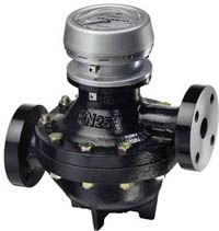
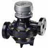
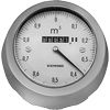
Rotary piston meter DN 25 (1") with single-pointer dial type 01
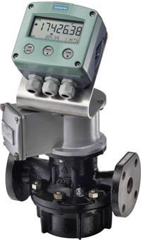
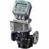
Rotary piston meter with electric flow register in compact form

Rotary piston meter DN 50 (2") with mech. single-pointer dial .type 01, with accessories (here: cooling attachment and pulser)
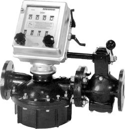
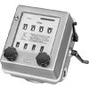
Automatic batchmeter DN 50 (2"), with rotary piston meter, quantity preset register and shut-off valve
Selection overview, rotary piston meters
Version
Rotary piston meters
Nominal diameter
DN 15
DN 25
DN 50
DN 80
Article No.
7MR10..-...
7MR11..-...
7MR14..-...
7MR16..-...
Nominal pressure
PN 6
•
PN 10
•
PN 16
•
•
PN 25
•
•
•
•
PN 40
•
•
•
PN 63
•
•
Flow variables
Max. 20 l/min
•
Max. 100 l/min
•
Max. 500 l/min
•
Max. 1 000 l/min
•
Flange standards
Drilled acc. to EN
•
•
•
•
Drilled acc. to ASME
•
•
•
•
With raised faces
•
•
•
•
Approvals
Custody transfer
•
•
•
Material acceptance test to EN 10204-3.1
•
•
•
•
ATEX
in preparation
Piston materials
Carbon
•
•
•
•
Cast iron
•
•
•
•
Ni-resist
•
•
•
Hard rubber
•
•
•
•
PTFE 40 °C
•
•
•
PTFE 90 °C
•
•
•
CrNiMo steel with carbon contact surface
•
CrNiMo steel with PTFE contact surface
•
PCTFE
•
•
•
Designs
Mechanical single-pointer dial
•
•
•
•
Mechanical double-pointer dial
•
•
•
•
As automatic batchmeter (incl. shut-off valve)
•
•
With electronic flow register
•
•
•
•
Remote or compact installation
•
•
•
•
Дизайн
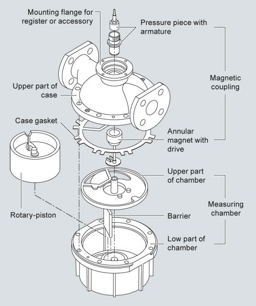
Metering mechanism of a rotary-piston meter DN 25/PN 10 (1“/MWP 145 psi) (industrial model)
The measuring chamber is inserted into the case for the rated pressure classes PN 25, PN 40 and PN 63 (MWP 363, 580 and 914 psi). The meters for rated pressures PN 4, PN 6 and PN 10 (MWP 58, 87 and 145 psi) have a measuring chamber machined to the lower part of the case.
All components of the meters are made of wear-resistant materials. Several materials are available for the parts which come into contact with the metered liquid (see Selection and Ordering data). The most suitable combination can be selected taking into account the corrosion resistance with respect to the liquid to be measured as well as the running characteristics and the permissible temperatures.
Конфигурация
Error curves of rotary-piston meters
The shape of the error curve is also affected by the viscosity of the metered liquid. The error in measurement increases with decreasing viscosity, especially at the beginning and towards the end of the flow rate range.
By appropriate regulation, i.e. changing a pair of gear-wheels between the meter mechanism and the register, the position of the error curve can be displaced parallel to the zero line and thus the meter can be optimally calibrated. The appropriate pair of replacement gears can be read off from a table or determined with the aid of a calculating disk.
The illustration “Error curves of volumetric meters” shows error curves without any regulation having been carried out.
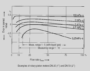
Error curves of volumetric meters dependent in shape and location on the flow rate and the viscosity of the liquid
Note: 1 mPa·s = 1 cp
Measuring accuracy
The rotary-piston meters are approved in the European Community and in many other countries for the custody transfer.
The following error limits apply between 0.2 % and 0.5 % of the correct value (depending on the liquid, the measuring range and the relevant calibration specifications).
The stated error limits in % of the correct value apply to the whole flow rate and for any delivery quantity greater than the smallest permissible quantity.
This is an important difference compared to other measuring instruments whose errors are related to the full-scale value and thus only reach the stated accuracy at one point - full-scale deflection. The minimum flow rate should not fall below 10 % of the maximum flow rate in order to remain within the stated accuracy limit. This explains why the usual flow rate range for volumetric meters is 1:10.
Note: The measuring system of the rotary-piston meter must always be filled with the liquid to be measured in order to achieve a high measuring accuracy.
Note
The material combinations which can be supplied are listed in the Selection and Ordering data.
The maximum permissible liquid temperature is determined by the “weakest link” in the particular combination (the PCTFE rotary-piston, for example, in a meter made of Cranium steel).Service life (long-term accuracy)
The service life of a volumetric meter, i.e. the operating time until an overhaul or recalibration becomes necessary, is determined by the mechanical abrasion of the moving parts of the mechanisms which occurs because of forces from the metered liquid.
As well as the nature of the materials used (running characteristics), the service life is dependent on the lubricating properties of the metered liquid, the service is dependent on the lubricating properties of the metered liquid, the daily operating time and the cube of the flow rate (speed of rotation). The last factor is one of the reasons why only half of the maximum flow rate specified for the batch operation is permissible for continuous operation.
Since the above factors can hardly be determined exactly with industrial use of the meter, unequivocal statements on the service life (long-term accuracy) are not possible.
Recalibration is required every two years by law (in Germany) for meters used for custody transfer. On the basis of this regulation, it is recommended that meters which are not used for custody transfer be checked and recalibrated if necessary, at intervals of two to three years. Even this recommendation is based on average, “normal” operating conditions. A period of three years is too short, for example, for a meter used for the batch dispensing of lubricating oil, it will still work within the stated error limits even after five years or more.
Rotary piston meters - Configurations
Mechanical displays
Digital displays
Compact design
As separate model
Compact design
Without pulse and current output
With pulse and current output
With pulse and current output
Incl. protective cover
With pulse and current output
Incl. mounting bracket
Registers
Single-pointer dial, type 01

•
•
•
Double-pointer dial, types 11 and 12
•
•
•
Quantity preset register
•
•
•
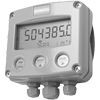
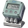
SITRANS F RA110 electric flow registers (7MV1070-...)
- Without mounting bracket
•
- With mounting bracket
•
Pulser
10 pulses/revolution,
100 pulses/revolution
•
•
10 pulses/value per revolution,
100 pulses/value per revolution•
Intermediate gear
(Part of Article No. of the rotary piston meter)
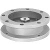
•
•
•
Pulser
10 Impulse/measuring chamber volumes
100 Impulse/measuring chamber volumes
(Selection with data position 14 of Article No. of the rotary piston meter)
•
Cooling attachment
Up to 80 °C: none
(Article No. 7MR1...-.....-....)
•
•
•
•
•
Up to 180 °C: one
(Article No. 7MR1...-.....-.... + 7MV3001-1xx00)Upt to 260 °C: two
(Article No. 7MR1...-.....-.... + 7MV3001-2xx00)Rotary piston meters and automatic batchmeters
Rotary piston meters
DN 15: 7MR10..-...
DN 25: 7MR11..-...
DN 50: 7MR14..-...
DN 80: 7MR16..-...
Automatic batchmeters
DN 25: 7MR111.-...
DN 50: 7MR141.-...
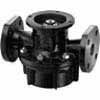
≤ PN 16

PN 25 … PN 63
•
•
•
•
•
Measuring chamber volumes:
DN 15 (1/2“): 0.033 l (0.0087 USgpm)
DN 25 (1“): 0.179 l (0.0473 USgpm)
DN 50 (2“): 1.5 l (0.317 USgpm)
DN 80 (3“): 4.32 l (1.14 USgpm)
Чертеж
Rotary-piston meter with single pointer dial and intermediate gear


DN 25
DN 50
DN 80
DN 15
DN 25
DN 50
DN 80
PN 25
PN 40
PN 25 und PN 40
PN 63
PN 25 und PN 40
PN 63
PN 25 und PN 40
PN 63
L
210 (8.27)
325 (12.80)
410 (16.14)
200 (7.87)
200 (7.87)
270 (10.63)
300 (11.81)
400 (15.75)
470 (18.50)
540 (21.26)
600 (23.62)
C
90 (3.54)
147 (5.79)
185 (7.28)
-
-
-
-
-
-
-
-
C1
-
-
-
50 (1.97)
68 (2.68)
80 (3.15)
82 (3.23)
120 (4.72)
120 (4.72)
155 (6.10)
177 (6.97)
C2
-
-
-
83,5 (5.67)
108 (4.25)
144 (5.67)
157 (6.18)
205 (8.07)
230 (9.06)
271 (10.67)
312 (12.28)
a3
153 (6.02)
205 (8.07)
244 (9.61)
140 (8.19)
165 (6.50)
208 (8.19)
224 (8.82)
263 (10.35)
285 (11.22)
331 (13.03)
387 (15.24)
Automatic batchmeter with quantity preset register intermediate gear
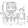
PN 25
PN 50
L1
210 (8.27)
325 (12.80)
L2
135 (5.31)
175 (6.89)
C
90 (3.54)
147 (5.79)
a3
153 (6.02)
205 (8.07)
In addition to dimension a3 the following dimensions need to be added for extra add-on components (dimensions in mm (inch))
Addition of
a3 +
Intermediate gear
37 (1.46)
Single-pointer dial type 01
47 (1.85)
Double-pointer dial type 11
58 (2.28)
Double-pointer dial type Typ 12
250 (9.84)
Pulser
82 (3.23)
Mounting bracket and electronic flow register
200 (7.87)
1 additional insulation attachment (up to 180°C (176°F))
159 (6.26)
2 additional insulation attachments
318 (12.52)
Quantity preset register
287 (11.30)
Особенности
- High measuring accuracy (approved for custody transfer)
- Suitable for flow rates up to 1000 l/min (264 USgpm)
- Wide flow rate range
- Low dependence on viscosity
- Low pressure drop
- Simple compact design
- High reliability
- Advantages with extremely high viscosity since pressure drops up to 3 bar (43.5 psi) permissible
- Advantages with very low viscosity (e. g. liquefied gas) since only low pressure drops occur because of the light-weight mechanism with good running characteristics
- Wide range of available materials, e. g. plastic lining for particularly corrosive liquids
- Easy service as a result of simple design
- Liquid temperatures up to 300 °C
- Also available with external heater
- Metering and dispensing without a power supply
- No inlet or outlet pipe sections required
- Independent of flow profile, conductivity and damping
Rotary-piston meters are characterized by:
- Accuracy
- Reliability
- Robust design
Технические данные
Further technical specifications
Materials and max. permissible liquid temperatures
Housing (also lining with acid resistant meters) and measuring chamber
Temperature range
- Cast iron, spheroidal graphite, cast steel, Cranium steel
-30 … +300 °C (-22 … +572 °F)
General data
Error limits
Between 0.2 % and 0.5 % of the correct value (depending on the metered fluid, the measuring range and the relevant calibration regulations) except for rotary-piston meters DN 15 (½“) and acid-resistant meters with PCTFE pistons; where 1 % of the actual value applies.
Reproducibility
Within 0.05 %
Adjustment
In steps from 0.01 %
Pressure drop
Max. permissible 3 bar (43.5 psi), max. 0.5 bar (7.25 psi) for acid resistant meters
Transmission from wet to dry space
Gland-free, via permanent magnet coupling
Installation position (axis of meter mechanism)
- Rotary-piston meter for industrial use
- Automatic batchmeter
Vertical
- Special designs
- Rotary-piston meter for oil fuels
Any
- Rotary-piston meter for liquid gas
Meter axis vertical
Special inlet and outlet pipe sections
Not necessary
Pipe connection
Flanges drilled to DIN 2501, DIN 2547 (PN 63 only)
Filter size (mesh width)
0.8 mm (0.031 inch) for rotary-piston meter
Meter sizes (DN), pressure stages (PN) and permissible flow rates (q) for rotary-piston meters and automatic batchmeters
Design
DN
PN
Rated flow rate
Permissible flow rate
With viscosity8)
Min.1) with continuous2) operation
Max. with intermittent3)4) operation
Max. with continuous operation
mm
(inch)
bar
(psi)
l/min
(USgpm)
mPa·s (cp)
l/min
(USgpm)
l/min
(USgpm)
l/min
(USgpm)
Rotary-piston meters for industrial use
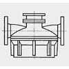
up to PN 16 (MWP 232 psi)
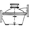
up to PN 63 (MWP 914 psi)
155)
(½)5)
25
(363)
20
(5.3)
≤ 1
< 5
800
20001.5
1.0
0.2
0.2(0.26)
(0.2)
(0.05)
(0.03)106)
20
20
10(5.3)
(5.3)
(5.3)
(1.3)10
10
10
5(2.6)
(2.6)
(2.6)
(1.3)25
(1)
10
16
25
40
63(145)
(232)
(363)
(580)
(914)100
(26.4)
0,3
0,6
1
5
80012
6
5
3
1(3.2)
(1.6)
(1.3)
(0.8)
(0.26)100
100
100
100
100(26)
(26)
(26)
(26)
(26)80
80
80
80
80(13)
(13)
(13)
(13)
(13)50
(2)
6
16
25
40
63(87)
(232)
(363)
(580)
(914)500
(132)
0.3
0.6
1
5
80040
20
18
10
2(11)
(5.3)
(4.8)
(2.6)
(0.53)500
500
500
500
500(106)
(132)
(132)
(132)
(106)350
350
350
350
350(44)
(44)
(44)
(44)
(44)80
(3)
25
40(363)
(580)1000
(264)
0.3
0.6
1
5
80060
35
25
10
5(16)
(9.3)
(6.6)
(2.6)
(1.3)1000
1000
1000
1000
1000(211)
(264)
(264)
(264)
(211)700
700
700
700
500(93)
(93)
(93)
(93)
(93)Automatic batchmeter (Rotary-piston meter with quantity preset register and mechanical shut-off valve)

25
(1)
10
(145)
100
(26.4)
0.3
0.6
1
5
8007)12
6
5
3
1(3.2)
(1.6)
(1.3)
(0.8)
(0.26)100
100
100
100
100(26)
(26)
(26)
(26)
(26)-
-
50
(2)
6
10(87)
(145)500
132
0.3
0.6
1
5
8007)40
20
18
10
2(11)
(5.3)
(4.8)
(2.6)
(0.53)500
500
500
500
400(106)
(132)
(132)
(132)
(106)-
-
1) For metal rotary-pistons: increase by a factor of 2, for PCTFE and PTFE/graphite filling rotary-pistons: increase by a factor of 3.
2) Continuous operation: over 8 hours a day.
3) For metal pistons: reduce by a factor ≈ 0.8 to extend service life
4) Intermittent operation: up to 8 hours a day
5) Note: When using pistons made of carbon, there is danger of break in the case of liquid hammers
6) When using pistons made of carbon.
7) Max. permissible viscosity for exact closing of the shut-off valve and for exact dispensing; viscosities up to around 4000 mPa·s (cp) possible.
8) Higher viscosity on request.
Note:
In order to extend the service life of the pulse sensor, rotary-piston meters with current and/or pulse output (without intermediate gear) should only be operated at max. 60 % of the permissible flow.Piston materials
Piston material
Design
Permissible liquid temperature (°C/°F)
Max. perm. dyn. Viscosity (mPa·s (cp))
Article No. code
Carbon
-10 … 300/14 … 572
25
K
Cast iron (mat. No. GG 25)
Cast iron (mat. No. GG 25)
with slotting-10 … 300/14 ... 572
-10 … 300/14 ... 572E
BNi-Resist (mat. No. 0.6660)
Ni-Resist (mat. No. 0.6660)
with slotting-10 … 300/14 ... 572
-10 … 300/14 ... 572N
CHard rubber
Hard rubber
with slotting-10 … +401)/14 ... 1041)
-10 … +401)/14 ... 1041)50
50G
DPTFE/graphite filling
PTFE/graphite filling
PTFE/graphite filling
PTFE/graphite filling
with slotting
with slotting0 … 402)/32 … 1042)
0 … 402)/32 … 1042)
0 … 902)/32 … 1942)
0 … 902)/32 … 1942)120
120
120
120F
L
R
MPCTFE
PCTFE
with slotting-10 … +402/14 … 1042)/
-10 … +402/14 … 1042)120
120H
JCrNi steel with carbon contact surface (only DN 25 (1“))
CrNi steel with PTFE contact surface (only DN 25 (1“))Collar piston
-10 … +200/14 ... 392
-10 … +40/14 ... 104> 10
> 10S
T1) For 120 min max. 65 °C (149 °F); for 20 min max. 90 °C (194 °F), e.g. for cleaning procedures
2) Error limit max. 1 %, at 90 °C (194 °F) max. 2 %.