
- Каталог оборудования Siemens
- Каталог продуктов Siemens Industry
- Приводная техника
- Техника автоматизации
- Системы автоматизации
- Системы визуализации SIMATIC HMI
- Системы идентификации
- Промышленные коммуникации SIMATIC NET
- Промышленные аппараты управления SIRIUS
- Промышленные информационные технологии
- Управление на базе РС
- Системы управления процессом
- Контрольно-измерительные приборы
- Измерительные преобразователи для давления
- Приборы измерения температуры SITRANS T
- Расходомеры
- Введение
- SITRANS F M электромагнитные расходомеры
- SITRANS F C - кориолисов массовый расходомер
- SITRANS F US - ультразвуковой расходомер
- SITRANS F X (Vortex)
- SITRANS F O delta p primary differential pressure devices
- SITRANS F R rotary-piston meters
- SITRANS F RA110 electric flow registers
- Pulsers with inductive pick-up
- Уровнемеры
- Позиционеры
- Устройство для защиты и пуска двигателей SIMOCODE-DP
- Сигнализаторы сбоев в промышленном процессе
- Аппаратные ПИД-регуляторы SIPART
- Встраиваемые самописцы и индикаторы
- Технологии взвешивания
- Дополнительные компоненты
- Коммуникации и программное обеспечение
- Directives
- Анализаторы процесса
- Блоки питания SITOP
- Продукты для специальных требований
- Energy
- Автоматизация и безопасность зданий
- Низковольтная коммутационная техника
- Технология безопасности
- Системные решения и продукты для отраслей
- Сервис
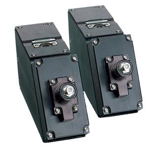
Flow sensor FSS200
- Информационные материалы
Область применения
Sensor type selection guide
Standard sensors supported in MLFB
Considerations for sensor selection
High precision
Universal
Notes
Media
General survey (clean liquids) on non-steel pipes
X
General survey (clean liquids) on a limited range of steel or non-steel pipes
X
Moderately aerated liquid or slurry, up to 121 °C (250 °F)
X
Permanent installation on steel pipe (clean liquids)
X
Installation in offshore or corrosive environment
X1)
X2)
Sensor size C/D/E come standard as corrosion resistant.
Size A and B optional stainless steelLiquid temperature greater than 120 °C (248 °F)
O
X
FSS200 high temperature metal block sensors (up to 230 °C (446 °F))
Operation on single pipeline flowing multiple products
X
O
Pipe material
Steel
X
Steel pipe with diameter/wall thickness ratio < 10
O
X
Non-steel pipe material (copper, ductile iron, cast iron, etc.)
O
X
High precision sensors can also be used on plastic and aluminum pipes in special cases
Wall thickness > 31.75 mm (1.25“)
O
X
O = not suitable
X = preferred choice
1) For steel and stainless steel pipes only
2) Not preferred for steel pipes
Definitions
Sensor chart
Description
Standard
Standard system sensor, plastic body with stainless steel housing, FM, FMc, ATEX, IECEx
Spare
Available, but not as part of a configured system. Ordered separately.
CE
All flowmeters and sensors are CE-certified
Ex-FM
Clamp-on sensors available as: Standard or corrosion resistant, suitable for frames or stainless steel-frames mounting, T1 or T2
Ex-ATEX
Option for all corrosion resistant, frames, weldseal, T1, T2
Corrosion resistant
Stainless steel construction
Trackless
Fixed only by straps, no other mounting (spacer bar as an option)
Tracks
For dedicated universal size A/B and for high precision size A/B. For all size high temperature applications
Frames
For dedicated universal size C/ D/ E, and for high precision size C/D
High precision mount
Special stainless steel frames. Corrosion resistant, liquid, T1, T2 usable from -40 ... +120 °C (-40 ... +248 °F)
but best for Ø temperature < 40 °C (104 °F), standardT1
Usable from -40 ... +120 °C (-40 ... +248 °F), but best for Ø temperature < 80 °C (< 176 °F);
named as high temperature high precisionT2
Usable -40 ... +120 °C (-40 ... +248 °F), but best for Ø temperature > 80 °C ( > 176 °F)
High temperature
Usable above -40 ... +120 °C (-40 ... +248 °F) to max. temperature 230 °C (446 °F)
Submersible
Sensors can be used in submersible applications using Denso wrap
Sensor Availability Guide
Availability
Sensor models
Standard
Spare only
ATEX/FM/FMc/IECEX
Corrosion resistant
Trackless
Tracks
Frames
FSS200 Universal Sensor -40 … 120 °C Stainless stelel housing CE IP68
A1 Universal for pipe OD – 5.8 … 50.8 mm (0.23" … 2")
X
X
X
X1)
X
A2 Universal for pipe OD – 12.7 … 50.8 mm (0.5" … 2")
X
X
X
X1)
X
B1 Universal for pipe OD – 12.7 … 76 mm (0.5" … 3")
X
X
X
X1)
X
X
B2 Universal for pipe OD – 12.7 … 76 mm (0.5" … 3")
X
X
X
X1)
X
X
B3 Universal for pipe OD – 19 … 127 mm (0.75" … 5")
X
X
X
X1)
X
X
C1 Universal for pipe OD – 51 … 254 mm (2" … 10")
X
X
X
X
X
C2 Universal for pipe OD – 51 … 254 mm (2" … 10")
X
X
X
X
X
C3 Universal for pipe OD – 51 … 305 mm (2" … 12")
X
X
X
X
X
D1 Universal for pipe OD – 102 … 508 mm (4" … 20")
X
X
X
X
X
D2 Universal for pipe OD – 152 … 610 mm (6" … 24")
X
X
X
X
X
D3 Universal for pipe OD – 203 … 610 mm (8" … 24")
X
X
X
X
X
*E1 Universal for pipe OD – 254 … 3048 mm (10" … 120")
X
X
X
X
X
*E2 Universal for pipe OD – 254 … 6096 mm (10" … 240")
X
X
X
X
X
*E3 Universal for pipe OD – 304 … 9144 mm (12" … 360")
X
X
X
X
X
1) Useable but not recommended for selection
Availability
Sensor models
High precidison mount
T1 (best use -40 … 65 °C)
T2 (best use 1 … 104 °C)
Submersible
Catalog
FSS200 Universal Sensor -40 … 120 °C Stainless steel housing CE IP68
A1 Universal for pipe OD – 5.8 … 50.8 mm (0.23" … 2")
X
A2 Universal for pipe OD – 12.7 … 50.8 mm (0.5" … 2")
X
X
B1 Universal for pipe OD – 12.7 … 76 mm (0.5" … 3")
X
B2 Universal for pipe OD – 12.7 … 76 mm (0.5" … 3")
X
B3 Universal for pipe OD – 19 … 127 mm (0.75" … 5")
X
X
C1 Universal for pipe OD – 51 … 254 mm (2" … 10")
X
C2 Universal for pipe OD – 51 … 254 mm (2" … 10")
X
C3 Universal for pipe OD – 51 … 305 mm (2" … 12")
X
X
D1 Universal for pipe OD – 102 … 508 mm (4" … 20")
X
D2 Universal for pipe OD – 152 … 610 mm (6" … 24")
X
D3 Universal for pipe OD – 203 … 610 mm (8" … 24")
X
X
* E1 Universal for pipe OD – 254 … 3048 mm (10" … 120")
X
* E2 Universal for pipe OD – 254 … 6096 mm (10" … 240")
X
X
* E3 Universal for pipe OD – 304 … 9144 mm (12" … 360")
X
X
1) Useable but not recommended for selection
Availability
Sensor models
Standard
Spare only
ATEX/FM/FMc/IECEX
Corrosion resistant
Trackless
Tracks
Frames
FSS200 High Precision Sensor -40 … 120 °C Alu T1 (T2, T3) CE
A1H (High Precision) for pipe WT -
0.64 ... 1.0 mm (0.025" ... 0.04")X
X
X
X1)
X
A2H (High Precision) for pipe WT -
1.0 ... 1.5 mm (0.04" ... 0.06")X
X
X
X1)
X
A3H (High Precision) for pipe WT -
1.5 ... 2.0 mm (0.06" ... 0.08")X
X
X
X1)
X
B1H (High Precision) for pipe WT -
2.0 ... 3.0 mm (0.08" ... 0.12")X
X
X
X1)
X
X
B2H (High Precision) for pipe WT -
3.0 ... 4.1 mm (0.12" ... 0.16")X
X
X
X1)
X
X
B3H (High Precision) for pipe WT -
2.7 ... 3.3 mm (0.106" ... 0.128")X
X
X
X1)
X
X
C1H (High Precision) for pipe WT (stainless steel construction) - 4.1 ... 5.8 mm (0.16" ... 0.23")
X
X
X
X
X
C2H (High Precision) for pipe WT (stainless steel construction) - 5.8 ... 8.1 mm (0..23" ... 0.32")
X
X
X
X
X
* D1H (High Precision) for pipe WT (stainless steel construction) - 8.1 ... 11.2 mm (0..32" ... 0.44")
X
X
X
X
X
* D2H (High Precision) for pipe WT (stainless steel construction) - 11.2 ... 15.7 mm (0.44" ... 0.62")
X
X
X
X
X
* D3H (High Precision) for pipe WT (stainless steel construction) - 7.4 ... 9.0 mm (0..293" ... 0.354")
X
X
X
X
X
* D4H (High Precision) for pipe WT (stainless steel construction) - 15.7 ... 31.8 mm (0..62" ... 1.25")
X
X
X
X
X
FSS200 High Temperature Universal Sensor -40 ... +230 °C (-40 ... +446 °F)
High Temperature size 1 ... 230 °C (Ø 12.7 ... 100 mm)
X
X
X
High Temperature size 2 ... 230 °C (Ø 30 ... 200 mm )
X
X
X
High Temperaturer size 3 ... 230 °C (Ø 150 ... 610 mm)
X
X
X
High Temperature size 4 ... 230 °C (Ø 400 ... 1200 mm)
X
X
X
High Temperature size 2A ... 230 °C (Ø 30 ... 200 mm)
X
X
X
High Temperature size 3A ... 230 °C (Ø 150 ... 610 mm)
X
X
X
High Temperature size 4A ... 230 °C (Ø 400 ... 1200 mm)
X
X
X
1) Useable but not recommended for selection
Availability
Sensor models
High Precision Mount
T1 (best use -40 … +65 °C)
T2 (best use 1 … 104 °C)
Submersible
Catalog
FSS200 High Precision Sensor -40 … 120 °C Alu T1 (T2, T3) CE IP68
A1H (High Precision) for pipe WT -
0.64 ... 1.0 mm (0.025" ... 0.04")X
X
X
A2H (High Precision) for pipe WT -
1.0 ... 1.5 mm (0.04" ... 0.06")X
X
X
A3H (High Precision) for pipe WT -
1.5 ... 2.0 mm (0.06" ... 0.08")X
X
X
B1H (High Precision) for pipe WT -
2.0 ... 3.0 mm (0.08" ... 0.12")X
X
X
X
B2H (High Precision) for pipe WT -
3.0 ... 4.1 mm (0.12" ... 0.16")X
X
X
X
B3H (High Precision) for pipe WT -
2.7 ... 3.3 mm (0.106" ... 0.128")X
X
X
X
C1H (High Precision) for pipe WT -
4.1 ... 5.8 mm (0.16" ... 0.23")X
X
X
X
X
C2H (High Precision) for pipe WT (stainless steel construction) - 5.8 ... 8.1 mm (0..23" ... 0.32")
X
X
X
X
X
* D1H (High Precision) for pipe WT (stainless steel construction) - 8.1 ... 11.2 mm (0..32" ... 0.44")
X
X
X
X
X
* D2H (High Precision) for pipe WT (stainless steel construction) - 11.2 ... 15.7 mm (0.44" ... 0.62")
X
X
X
X
X
* D3H (High Precision) for pipe WT (stainless steel construction) - 7.4 ... 9.0 mm (0..293" ... 0.354")
X
X
X
X
X
* D4H (High Precision) for pipe WT (stainless steel construction) - 15.7 ... 31.8 mm (0..62" ... 1.25")
X
X
X
X
X
FSS200 High Temperature Universal Sensor -40 ... +230 °C (-40 ... +446 °F)
High Temperature size 1 ... 230 °C (Ø 12.7 ... 100 mm)
High Temperature size 2 ... 230 °C (Ø 30 ... 200 mm )
X
High Temperaturer size 3 ... 230 °C (Ø 150 ... 610 mm)
X
High Temperature size 4 ... 230 °C (Ø 400 ... 1200 mm)
X
High Temp. size 2A ... 230 °C (Ø 30 ... 200 mm)
High Temp. size 3A ... 230 °C (Ø 150 ... 610 mm)
High Temp. size 4A ... 230 °C (Ø 400 ... 1200 mm)
1) Useable but not recommended for selection
Sensor mounting availability guide
Sensor
FSS200
Universal dedicatedFSS200
Dedicated
liquid flow high precision sensorsFSS200
High temperature
universal sensorsMounting
Trackless
X
X
Tracks universal dedicated
X
Tracks HP dedicated
X
Frames universal dedicated
X
Frames HP dedicated
X
Tracks high temperature universal
X
High precision mounting single enclosure
X
High precision mounting dual enclosure
X
SpacerBar
X
X
Straps
X
X
X
Chains EZ-Clamp 1
Size C, D
Size C
Chains EZ-Clamp 2
Size E
Size D
Denso
X
X
1) Usable but not recommended
Функции
Operating Principle
The SITRANS F S system is a transit-time ultrasonic meter that provides exceptional performance using a non-intrusive clamp-on approach. Ultrasonic sensors transmit and receive acoustic signals directly though the existing pipe wall, where the fluid refraction angle is governed by Snell’s law of refraction.
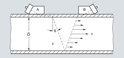
Clamp-on sensor mounted in a reflect configuration
The beam refraction angle is calculated as follows:
sin Ө = c / Vφ
c = Velocity of sound in fluid
Vφ = Phase velocity (a constant in the pipe wall)
The flowmeter automatically compensates for any change in fluid sound velocity (or beam angle) in response to variations in the average transit time between sensors A and B. By subtracting the computed fixed times (within the sensor and pipe wall) from the measured average transit time, the meter can then infer the required transit time in the fluid (TFluid).
The sound waves traveling in the same direction as the flow (TA,B) arrive earlier than sound waves traveling against the direction of flow (TB,A). This time difference (Δt) is used to compute the line integrated flow velocity (v) as shown in the equation below:
v = Vφ / 2 · Δt / TFluid
Once the raw flow velocity is determined, the fluid Reynolds Number (Re) must be determined to properly correct for fully developed flow profile. This requires the entry of the fluid’s kinematic viscosity (visc) as shown in the equations below, where Q represents the final flow profile compensated volumetric flow rate.
Re = Di · v / visc Q = K(Re) · ( π / 4 ·Di2 ) · v
v = Flow velocity
visc = μ / ρ = (dynamic viscosity / density)
K(Re) = Reynolds flow profile compensation
In wetted type ultrasonic flowmeters the meter constants are configured prior to leaving the factory. As this is not possible with clamp-on meters, the settings must be made by the customer at the time of installation. These settings include pipe diameter, wall thickness, liquid viscosity, etc.
SITRANS clamp-on flowmeters that include temperature sensing can be configured to dynamically infer changes in fluid viscosity for the purpose of computing the most accurate flow profile compensation (KRe).
Ultrasonic sensor types
Two basic types of clamp-on sensors can be selected for use with the SITRANS F S flowmeter. The lower cost "universal" sensor is the most common type in the industry and is suitable for most single liquid applications where the sound velocity does not vary much. This sensor type can be used on any sonically conductive pipe material (including steel) making it well suited for portable survey applications. Universal sensors are selected based on the pipe diameter range alone, so wall thickness is less important to the selection process.
The second sensor type is the patented "WideBeam" sensor (called high precision), which utilizes the pipe wall as a kind of waveguide to optimize the signal to noise ratio and provide a wider area of vibration. This makes this kind of sensor less sensitive to any change in the fluid medium.
The WideBeam sensor is designed for steel pipes, but can also be used with aluminum and titanium. It is the preferred sensor for HPI applications. Note that unlike the universal type, this sensor selection is dependent only on the pipe’s wall thickness.
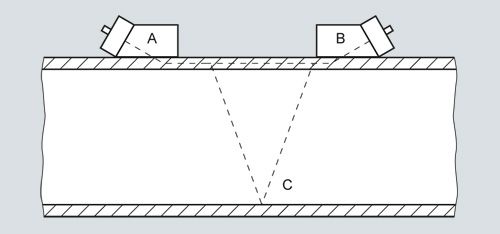
Multi-path flowmeters
For improved flow profile averaging, redundancy or better cost per measurement, clamp-on meters can be supplied with 1 or 2 path measurement systems.
In the standard FS230 systems, these can be installed on a single pipe as shown below (two paths on same pipe).

Dual path installation example
SITRANS meter family description
SITRANS FS230 clamp-on flowmeters
The FS230 system is a basic function, permanent (or dedicated) Clamp-on meter that is available with a full range of safety approvals and I/Os. This meter can be used in a wide range of applications.
FST030 transmitter standard flow functions
When configured with standard flow functions, the FST030 transmitter is typically programmed with a fixed viscosity and specific gravity entry, which can limit the mass flow and volumetric flow accuracy when highly variable (multi-product) liquid properties flow through the same pipeline.
It will have the ability to accommodate clamp-on RTDs, or analog input from a temperature transmitter.
FST030 hydrocarbon flow functions
When configured with hydrocarbon functions, the FST030 can be used for applications that will flow a wide range of viscosity with a standard volume (mass) and interface detection functions available. All functions rely on a variable referred to as "LiquIdent (TM)", which is used to infer the liquid’s viscosity and density. This variable represents the measured liquid sonic velocity compensated by the operating temperature and pressure, so for a given liquid product the measured LiquIdent (TM) output will remain constant over a wide range of pressure or temperature.
Standard volume description:
This LiquIdent (TM) variable can also be used to identify the liquid flowing through the pipe as well as it’s physical properties (density, vicosity and compressibility) at base conditions. With this information the meter can be configured to output a temperature and pressure compensated (standard) volume flow rate using the API MPMS chapter 11.2.1 methods as shown below.
Correction for temperature:
Compute thermal expansion coefficient (αb):
αb = KO / ρb2 + K1 / ρb
where:
KO and K1 are constants dependent on type of liquid and ρb is the liquid density at base conditions
Compute temperature correction factor (KT):
KT = ρb * EXP (- αb ΔT (1 + 0.8 αb ΔT))
where:
ΔT = (T – base temperature)
Correction for pressure:
Compute compressibility factor (F):
F = EXP(A + B T + (C + D T) / ρb2
where:
A, B, C and D are constants, and "T" is liquid temperature
Compute pressure correction factor (Kp):
Kp = 1 / (1 – F (Pact – Pbase) * 10-4)
Final volume correction: Qstd = Qact * Kt * Kp
Available outputs from this meter include: API, standard density, mass flowrate, standard volume flowrate and liquid identification.
General installation guidelines for transit time clamp-on sensor
- Minimum measuring range: 0 to ± 0.3 m/s velocity (see meter accuracy graph below for more detail)
- Maximum measuring range: 0 to ± 12 m/s (± 30 m/s for high precision sensors). Final flow range determination requires application review
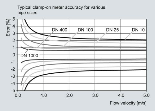
- Pipe must be completely full within the sensor installation volume for accurate flow measurement
- Typical MINIMUM straight pipe requirements are: 10 Diameters upstream / 5 Diameters downstream. Additional straight run is required for double out-of-plane elbows and partially open valves. A minimum of 20 upstream diameters is recommended for clamp-on gas systems
- Sensors should be installed at least 20° off vertical for horizontal pipes. This reduces the chance of beam interference from gas buildup at the top of the pipe
- Operation inside the Reynolds transition region, between 1 000 < Re < 5 000 should be avoided for best accuracy
- Submersible and direct burial installations can be accommodated. Consult sales representative for details
- Ultrasonic coupling compound is provided with all sensor orders. Insure that a permanent coupling compound is used for long term installations
- Refer to the "Sensor type selection guide" to insure proper application of the equipment