
- Каталог оборудования Siemens
- Каталог продуктов Siemens Industry
- Приводная техника
- Преобразователи
- Стандартные преобразователи
- Общая информация о базовых преобразователях SINAMICS V
- Преобразователи частоты общего назначения SINAMICS G
- Высокопроизводительные преобразователи SINAMICS S
- Сервопреобразователь SINAMICS S110
- SINAMICS S120
- SINAMICS S120M distributed servo drive
- SINAMICS S120 Combi
- SINAMICS S120 Chassis Format Units
- Air-cooled units
- Liquid-cooled units
- System components
- Line-side power components
- DC link components
- Motor-side power components
- Control Units
- Supplementary system components
- BOP20 Basic Operator Panel
- AOP30 Advanced Operator Panel
- CBC10 Communication Board
- CBE20 Communication Board
- DMC20 DRIVE-CLiQ Hub Module
- DME20 DRIVE-CLiQ Hub Module
- TB30 Terminal Board
- TM15 Terminal Module
- TM31 Terminal Module
- TM31 Terminal Module
- TM41 Terminal Module
- TM54F Terminal Module
- TM120 Terminal Module
- TM150 Terminal Module
- VSM10 Voltage Sensing Module
- Safe Brake Adapter SBA
- Encoder system connection
- Connection system
- SINAMICS S120 Cabinet Modules
- SINAMICS S150 converter cabinet units
- MICROMASTER
- SIPLUS POSMO A
- SIMODRIVE POSMO
- LOHER DYNAVERT Drive System
- Преобразователи на среднее напряжение
- Преобразователи постоянного тока
- Стандартные преобразователи
- Двигатели переменного тока
- Generators
- Мотор-редукторы
- Flender Gear Units
- Couplings
- Инструментальное программное обеспечение
- Дополнительные компоненты
- Преобразователи
- Техника автоматизации
- Energy
- Автоматизация и безопасность зданий
- Низковольтная коммутационная техника
- Технология безопасности
- Системные решения и продукты для отраслей
- Сервис
- Приводная техника
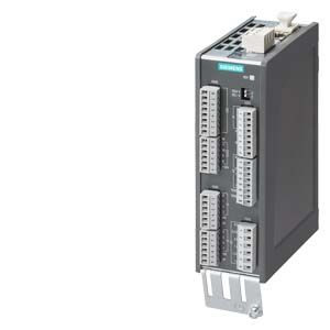
TM31 Terminal Module
- Заказные данные (1)
- Аксессуары (1)
- Информационные материалы
Информационные материалы
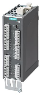
TM31 Terminal Module
With the TM31 Terminal Module, the number of available digital inputs and outputs and the number of analog input and outputs within a drive can be expanded.
The TM31 Terminal Module also features relay outputs with changeover contact and a temperature sensor input.
Дизайн
The following are located on the TM31 Terminal Module:
- 8 digital inputs
- 4 bidirectional digital inputs/outputs
- 2 relay outputs with changeover contact
- 2 analog inputs
- 2 analog outputs
- 1 temperature sensor input for KTY84‑130, Pt1000 or PTC (Pt1000 can be used from firmware V4.7 HF17)
- 2 DRIVE‑CLiQ sockets
- 1 connection for the electronics power supply via the 24 V DC supply connector
- 1 PE (protective earth) connection
The status of the TM31 Terminal Module is indicated via a multi-color LED.
The TM31 Terminal Module can be snapped onto a TH 35 standard mounting rail in accordance with EN 60715 (IEC 60715).
The signal cable shield can be attached to the TM31 Terminal Module via a shield connection terminal, e.g. type SK8 supplied by Phoenix Contact or type KLBÜ CO 1 supplied by Weidmüller. The shield connection terminal must not be used as a strain relief mechanism.
Интеграция
The TM31 Terminal Module can communicate via DRIVE‑CLiQ with the following Control Units.
- CU310‑2 Control Unit
- CU320‑2 Control Unit
- SINUMERIK Control Unit
- SIMOTION D Control Unit
- SINAMICS DCM Advanced CUD
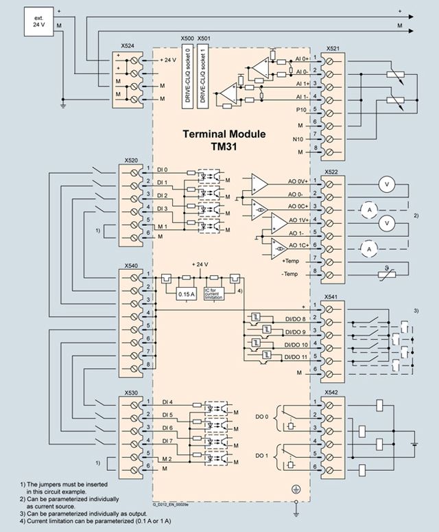
Connection example of TM31 Terminal Module
Технические данные
TM31 Terminal Module
6SL3055-0AA00-3AA1
Current requirement, max.
At 24 V DC without taking account of the digital outputs and DRIVE-CLiQ supply
0.5 A
- Conductor cross-section, max.
2.5 mm2
- Fuse protection, max.
20 A
Digital inputs
In accordance with IEC 61131‑2 Type 1
- Voltage
-3 ... +30 V
- Low level
(an open digital input is interpreted as "low")
-3 ... +5 V
- High level
15 ... 30 V
- Current consumption at 24 V DC, typ.
9 mA
- Delay times of digital inputs 1), approx.
- L → H
50 μs
- H → L
100 μs
- Conductor cross-section, max.
1.5 mm2
Digital outputs
(continuously short-circuit proof)
- Voltage
24 V DC
- Load current per digital output, max.
100 mA
- Total current of digital outputs, max.
400 mA
- Delay times of digital outputs 1)
- Typ.
150 μs with 0.5 A resistive load
- Max.
500 μs
- Conductor cross-section, max.
1.5 mm2
Analog inputs
(a switch is used to toggle between voltage and current input)
- As voltage input
- Voltage range
-10 ... +10 V
- Internal resistance Ri
100 kΩ
- Resolution 2)
11 bits + sign
- As current input
- Current ranges
4 ... 20 mA, -20 ... +20 mA, 0 ... 20 mA
- Internal resistance Ri
250 Ω
- Resolution 2)
10 bits + sign
- Conductor cross-section, max.
1.5 mm2
Analog outputs
(continuously short-circuit proof)
- Voltage range
-10 ... +10 V
- Max. load current
-3 ... +3 mA
- Current ranges
4 ... 20 mA, -20 ... +20 mA, 0 ... 20 mA
- Load resistance, max.
500 Ω in the range -20 ... +20 mA
- Resolution
11 bits + sign
- Conductor cross-section, max.
1.5 mm2
Relay outputs
(CO contacts)
- Max. load current
8 A
- Operational voltage, max.
250 V AC, 30 V DC
- Switching capacity, max.
- At 250 V AC
2000 VA (cos φ = 1)
750 VA (cos φ = 0.4)- At 30 V DC
240 W (resistive load)
- Required minimum current
100 mA
- Conductor cross-section, max.
2.5 mm2
Power loss, max.
10 W
PE connection
M4 screw
Dimensions
- Width
50 mm (1.97 in)
- Height
150 mm (5.91 in)
- Depth
111 mm (4.37 in)
Weight, approx.
0.49 kg (1.08 lb)
Certificate of suitability
cULus
1) The specified delay times refer to the hardware. The actual reaction time depends on the time slot in which the digital input/output is processed.
2) If the analog input is to be operated in the signal processing sense with continuously variable input voltage, the sampling frequency fa = 1/ttime slice must be at least twice the value of the highest signal frequency fmax.