
- Каталог оборудования Siemens
- Каталог продуктов Siemens Industry
- Приводная техника
- Преобразователи
- Стандартные преобразователи
- Общая информация о базовых преобразователях SINAMICS V
- Преобразователи частоты общего назначения SINAMICS G
- Высокопроизводительные преобразователи SINAMICS S
- Сервопреобразователь SINAMICS S110
- SINAMICS S120
- SINAMICS S120M distributed servo drive
- SINAMICS S120 Combi
- SINAMICS S120 Chassis Format Units
- Air-cooled units
- Liquid-cooled units
- System components
- Line-side power components
- DC link components
- Motor-side power components
- Control Units
- Supplementary system components
- BOP20 Basic Operator Panel
- AOP30 Advanced Operator Panel
- CBC10 Communication Board
- CBE20 Communication Board
- DMC20 DRIVE-CLiQ Hub Module
- DME20 DRIVE-CLiQ Hub Module
- TB30 Terminal Board
- TM15 Terminal Module
- TM15 Terminal Module
- TM31 Terminal Module
- TM41 Terminal Module
- TM54F Terminal Module
- TM120 Terminal Module
- TM150 Terminal Module
- VSM10 Voltage Sensing Module
- Safe Brake Adapter SBA
- Encoder system connection
- Connection system
- SINAMICS S120 Cabinet Modules
- SINAMICS S150 converter cabinet units
- MICROMASTER
- SIPLUS POSMO A
- SIMODRIVE POSMO
- LOHER DYNAVERT Drive System
- Преобразователи на среднее напряжение
- Преобразователи постоянного тока
- Стандартные преобразователи
- Двигатели переменного тока
- Generators
- Мотор-редукторы
- Flender Gear Units
- Couplings
- Инструментальное программное обеспечение
- Дополнительные компоненты
- Преобразователи
- Техника автоматизации
- Energy
- Автоматизация и безопасность зданий
- Низковольтная коммутационная техника
- Технология безопасности
- Системные решения и продукты для отраслей
- Сервис
- Приводная техника
TM15 Terminal Module
- Заказные данные (1)
- Аксессуары (1)
- Информационные материалы
Информационные материалы
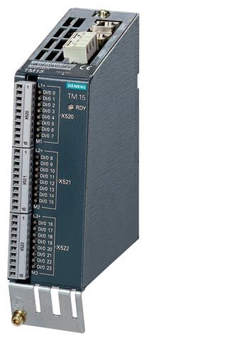
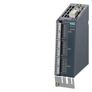
TM15 Terminal Module
The number of available digital inputs and outputs within a drive system can be expanded with the TM15 Terminal Module.
Дизайн
The TM15 Terminal Module is equipped with the following:
- 24 bidirectional digital inputs/outputs (electrical isolation in 3 groups with 8 channels per group)
- 24 green status LEDs for indicating the logical signal state of the corresponding terminal
- 2 DRIVE-CLiQ sockets
- 1 connection for the electronics power supply via the 24 V DC power supply connector
- 1 PE (protective earth) connection
The status of the TM15 Terminal Module is indicated via a multi-color LED.
The TM15 Terminal Module can be snapped onto a TH 35 standard mounting rail in accordance with EN 60715 (IEC 60715).
The signal cable shield can be connected to the TM15 Terminal Module by means of a shield connection terminal, e.g. Phoenix Contact type SK8 or Weidmüller type KLBÜ CO 1. The shield connection terminal must not be used as a strain relief mechanism.
Интеграция
The TM15 Terminal Module can communicate with the following Control Units via DRIVE‑CLiQ:
- CU310‑2 Control Unit
- CU320‑2 Control Unit
- SINUMERIK Control Unit
- SIMOTION D Control Unit
- SINAMICS DCM Advanced CUD
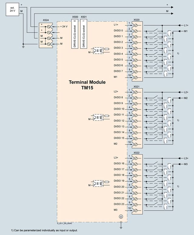
Connection example of TM15 Terminal Module
Технические данные
TM15 Terminal Module
6SL3055-0AA00-3FA0
Current requirement, max.
at 24 V DC without load
0.15 A
- Conductor cross-section, max.
2.5 mm2
- Fuse protection, max.
20 A
Number of DRIVE‑CLiQ sockets
2
I/O
- Digital inputs/outputs
Parameterizable channel-by-channel as DI or DO
- Number of digital inputs/outputs
24
- Isolation
Yes, in groups of 8
- Cables and connections
Plug-in screw-type terminals
- Conductor cross-section, max.
1.5 mm2
Digital inputs
- Voltage
-30 ... +30 V
- Low level
(an open digital input is interpreted as "low")
-30 ... +5 V
- High level
15 ... 30 V
- Current consumption at 24 V DC
9 mA
- Delay times of digital inputs, typ.1)
- L → H
50 μs
- H → L
100 μs
Digital outputs
(continuously short-circuit proof)
- Voltage
24 V DC
- Load current per digital output, max.
0.5 A
- Delay times (resistive load) 1)
- L → H, typ.
50 μs
- L → H, max.
100 μs
- H → L, typ.
150 μs
- H → L, max.
225 μs
- Total current of outputs
(per group), max.
- To 60 °C (140 °F)
2 A
- To 50 °C (122 °F)
3 A
- To 40 °C (104 °F)
4 A
Power loss, max.
3 W
PE connection
M4 screw
Dimensions
- Width
50 mm (1.97 in)
- Height
150 mm (5.91 in)
- Depth
111 mm (4.37 in)
Weight, approx.
1 kg (2.20 lb)
Certificate of suitability
cULus
1) The specified delay times refer to the hardware. The actual reaction time depends on the time slot in which the digital input/output is processed.