
- Каталог оборудования Siemens
- Каталог продуктов Siemens Industry
- Приводная техника
- Техника автоматизации
- Системы автоматизации
- Системы визуализации SIMATIC HMI
- Системы идентификации
- Промышленные коммуникации SIMATIC NET
- Промышленные аппараты управления SIRIUS
- Промышленные информационные технологии
- Управление на базе РС
- Системы управления процессом
- Контрольно-измерительные приборы
- Измерительные преобразователи для давления
- Приборы измерения температуры SITRANS T
- Расходомеры
- Введение
- SITRANS F M электромагнитные расходомеры
- SITRANS F C - кориолисов массовый расходомер
- SITRANS F US - ультразвуковой расходомер
- SITRANS F X (Vortex)
- SITRANS F O delta p primary differential pressure devices
- SITRANS F R rotary-piston meters
- SITRANS F RA110 electric flow registers
- Pulsers with inductive pick-up
- Уровнемеры
- Позиционеры
- Устройство для защиты и пуска двигателей SIMOCODE-DP
- Сигнализаторы сбоев в промышленном процессе
- Аппаратные ПИД-регуляторы SIPART
- Встраиваемые самописцы и индикаторы
- Технологии взвешивания
- Дополнительные компоненты
- Коммуникации и программное обеспечение
- Directives
- Анализаторы процесса
- Блоки питания SITOP
- Продукты для специальных требований
- Energy
- Автоматизация и безопасность зданий
- Низковольтная коммутационная техника
- Технология безопасности
- Системные решения и продукты для отраслей
- Сервис
SITRANS FX330
- Заказные данные (2)
- Информационные материалы
Информационные материалы
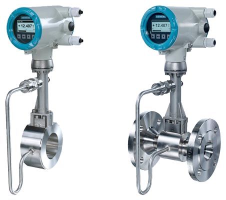
SITRANS FX vortex flowmeter are designed for use in industrial applications and optimally suited to the demands in auxiliary supply systems.
The proven principle of vortex flowmeters is suitable for measure-ment of liquids, gases and vapors unaffected by conductivity, viscosity, temperature and pressure.
Область применения
- Measurement of saturated steam and superheated steam
- Steam boiler monitoring
- Heat metering of steam and hot water
- Measurement of consumption of industrial gases
- Measurement of consumption in compressed air systems
- Monitoring of compressor output
- Evaluation of Free Air Delivery (FAD)
- SIP and CIP processes in the food, beverage and pharmaceutical industries
- Measuring of conductive and non-conductive liquids
- Safety-related measurement in SIL applications (SIL2)
Gross and net heat quantity calculation
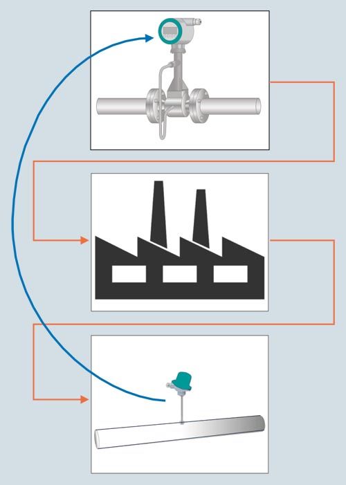
The SITRANS FX330 was designed for applications in auxiliary and supply service lines, such as internal monitoring of energy flows for saturated and superheated steam or hot water. Equipped with temperature sensor as standard, the device can be installed as heat meter in the feed line directly connected with an external temperature sensor in the return line. The gross and net heat calculation can be fed into a DCS to support advanced energy management.
When it comes to energy, the most accurate measurement of consumption is essential. By combining flow, temperature and pressure measurements in one device, SITRANS FX330 provides the basis for a precise mass flow calculation.
In steam applications, the software even determines the enthalpy - the heat content - of the steam. Therefore, SITRANS FX330 is able to calculate the gross heat quantity.
In case net heat quantity consumption of process is asked for, a single temperature sensor can be added to the return line. SITRANS FX330 uses the readings to calculate the amount of heat consumed.
The SITRANS FX330 thereby proves itself to be a reliable partner.
Дизайн
SITRANS FX330
Flange
SITRANS FX330
Sandwich
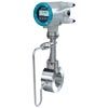
Flange version with integrated temperature compensation as standard for saturated steam and optional pressure compensation for superheated steam, gases and wet gases.
All advantages of the flange version in a space-saving sandwich design; centering rings guarantee an easy installation without any offset.
Integrated reduction of nominal diameter for space-saving and economic installations plus large measuring ranges.
Integrated reduction of nominal diameter not available
Also in remote design with field housing and connection cable up to 50 m (164 ft)
With shut off valve allowing
- exchange and calibration of pressure sensor
- pressure and leak testing of pipeline
without interrupting the process.
Функции
Vortex flowmeters are used to measure the flow of gases, vapors and liquids in completely filled pipes. The measuring principle is based on the principle of the Karman vortex street. Inside the measuring sensor vortices are shed from a bluff body and are detected by a sensor located behind. The frequency f of the vortex shedding is proportional to the flow velocity v.
The nondimensional Strouhal number S describes the relationshipbetween vortex frequency f, width b of the bluff body andthe mean flow velocity v:
f = (S . v) / b
The vortex frequency is recorded at the sensor and evaluated at the converter.

Functional principle
Конфигурация
Available combinations of sensors and connection size for SITRANS FX330 in flanged design are shown in the table below.
Sensor size
Connection size
EN 1092-1, Form B1/B2, PN 10
EN 1092-1, Form B1/B2, PN 16
EN 1092-1, Form B1/B2, PN 25
EN 1092-1, Form B1/B2, PN 40
EN 1092-1, Form B1/B2, PN 63
EN 1092-1, Form B1/B2, PN 100
ANSI B16.5, class 150
ANSI B16.5, class 300
ANSI B16.5, class 600
SITRANS FX330 Flanged (7ME2610-...)
DN15
DN 15
-
-
-
x
-
x
x
x
x
DN 25
-
-
-
x
-
x
x
x
x
DN 40
-
-
-
x
-
x
x
x
x
DN 25
DN 25
-
-
-
x
-
x
x
x
x
DN 40
-
-
-
x
-
x
x
x
x
DN 50
-
x
-
x
x
x
x
x
x
DN 40
DN 40
-
-
-
x
-
x
x
x
x
DN 50
-
x
-
x
x
x
x
x
x
DN 80
-
x
-
x
x
x
x
x
x
DN 50
DN 50
-
x
-
x
x
x
x
x
x
DN 80
-
x
-
x
x
x
x
x
x
DN 100
-
x
-
x
x
x
x
x
x
DN 80
DN 80
-
x
-
x
x
x
x
x
x
DN 100
-
x
-
x
x
x
x
x
x
DN 150
-
x
-
x
x
x
x
x
x
DN 100
DN 100
-
x
-
x
x
x
x
x
x
DN 150
-
x
-
x
x
x
x
x
x
DN 200
x
x
x
x
-
-
x
x
-
DN 150
DN 150
-
x
-
x
x
x
x
x
x
DN 200
x
x
x
x
-
-
x
x
-
DN 250
x
x
x
x
-
-
x
x
-
DN 200
DN 200
x
x
x
x
-
-
x
x
-
DN 250
x
x
x
x
-
-
x
x
-
DN 300
x
x
x
x
-
-
x
x
-
DN 250
DN 250
x
x
x
x
-
-
x
x
-
DN 300
x
x
x
x
-
-
x
x
-
DN 300
DN 300
x
x
x
x
-
-
x
x
-
x available
- not available
Чертеж
Compact version
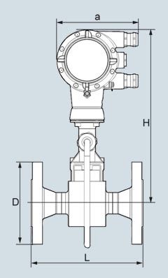
SITRANS FX330 (Vortex), Flanged version with pressure sensor, front view
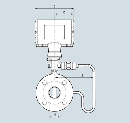
SITRANS FX330 (Vortex), Flanged version with pressure sensor, side view
Flange version EN 1092-1
Size
Pressure rating
Dimensions [mm (inch)]
a = 148.5 (5.85), b = 85.8 (3.38), c = 171.5 (6.76)Weight [kg (lb)]
DN
PN
d
d
FR1)d
FR2)D
L
H
l
Flowmeter (without pressure sensor)
Flowmeter (with pressure sensor)
15
40
17.3 (0.68)
-
-
95 (3.74)
200 (7.87)
308.8 (12.16)
169.3 (6.67)
5.5 (12.13)
6.1 (13.45)
15
100
17.3 (0.68)
-
-
105 (4.13)
200 (7.87)
308.8 (12.16)
169.3 (6.67)
6.5 (14.33)
7.1 (15.65)
25
40
28.5 (1.12)
17.3 (0.68)
-
115 (4.53)
200 (7.87)
308.8 (12.16)
169.3 (6.67)
7.3 (16.09)
7.9 (17.42)
25
100
28.5 (1.12)
17.3 (0.68)
-
140 (5.51)
200 (7.87)
308.8 (12.16)
169.3 (6.67)
9.3 (20.50)
9.9 (21.83)
40
40
43.1 (1.70)
28.5 (1.12)
17.3 (0.68)
150 (5.91)
200 (7.87)
312.3 (12.30)
169.5 (6.67)
10.2 (22.49)
10.8 (23.81)
40
100
42.5 (1.67)
28.5 (1.12)
17.3 (0.68)
170 (6.69)
200 (7.87)
312.3 (12.30)
169.5 (6.67)
14.2 (31.31)
14.8 (32.63)
50
16
54.5 (2.15)
42.5 (1.67)
28.5 (1.12)
165 (6.50)
200 (7.87)
318.3 (12.53)
169.3 (6.67)
12.1 (26.68)
12.7 (28.00)
50
40
54.5 (2.15)
42.5 (1.67)
28.5 (1.12)
165 (6.50)
200 (7.87)
318.3 (12.53)
169.3 (6.67)
12.3 (27.12)
12.9 (28.44)
50
63
54.5 (2.15)
42.5 (1.67)
28.5 (1.12)
180 (7.09)
200 (7.87)
318.3 (12.53)
169.3 (6.67)
16.3 (35.94)
16.9 (37.26)
50
100
53.9 (2.12)
42.5 (1.67)
28.5 (1.12)
195 (7.68)
200 (7.87)
318.3 (12.53)
169.3 (6.67)
17.8 (39.24)
18.4 (40.57)
80
16
82.5 (3.25)
54.5 (2.15)
42.5 (1.67)
200 (7.87)
200 (7.87)
330.3 (13.00)
169.3 (6.67)
16.8 (37.04)
17.4 (38.36)
80
40
82.5 (3.25)
54.5 (2.15)
42.5 (1.67)
200 (7.87)
200 (7.87)
330.3 (13.00)
169.3 (6.67)
18.8 (41.45)
19.4 (42.77)
80
63
81.7 (3.22)
54.5 (2.15)
42.5 (1.67)
215 (8.46)
200 (7.87)
330.3 (13.00)
169.3 (6.67)
22.8 (50.27)
23.4 (51.59)
80
100
80.9 (3.19)
54.5 (2.15)
42.5 (1.67)
230 (9.06)
200 (7.87)
330.3 (13.00)
169.3 (6.67)
26.8 (59.08)
27.4 (60.41)
100
16
107 (4.21)
80.9 (3.19)
54.5 (2.15)
220 (8.66)
250 (9.84)
346.8 (13.65)
171.5 (6.75)
21.4 (47.18)
22 (48.50)
100
40
107 (4.21)
80.9 (3.19)
54.5 (2.15)
235 (9.25)
250 (9.84)
346.8 (13.65)
171.5 (6.75)
24.4 (53.79)
25 (55.12)
100
63
106 (4.17)
80.9 (3.19)
54.5 (2.15)
250 (9.84)
250 (9.84)
346.8 (13.65)
171.5 (6.75)
29.4 (64.82)
30 (66.14)
100
100
104 (4.09)
80.9 (3.19)
54.5 (2.15)
265 (10.43)
250 (9.84)
346.8 (13.65)
171.5 (6.75)
35.4 (78.04)
36 (79.37)
150
16
159 (6.26)
107 (4.21)
80.9 (3.19)
285 (11.22)
300 (11.81)
366.3 (14.42)
191.5 (7.54)
35.2 (77.60)
35.8 (78.93)
150
40
159 (6.26)
107 (4.21)
80.9 (3.19)
300 (11.81)
300 (11.81)
366.3 (14.42)
191.5 (7.54)
41.2 (90.83)
41.8 (92.15)
150
63
157 (6.18)
107 (4.21)
80.9 (3.19)
345 (13.58)
300 (11.81)
366.3 (14.42)
191.5 (7.54)
59.2 (130.51)
59.8 (131.84)
150
100
154 (6.06)
107 (4.21)
80.9 (3.19)
355 (13.98)
300 (11.81)
366.3 (14.42)
191.5 (7.54)
67.2 (148.15)
67.8 (149.47)
200
10
207 (8.15)
159 (6.26)
107 (4.21)
340 (13.39)
300 (11.81)
392.1 (15.44)
202.8 (7.98)
37.8 (83.33)
38.4 (84.66)
200
16
207 (8.15)
159 (6.26)
107 (4.21)
340 (13.39)
300 (11.81)
392.1 (15.44)
202.8 (7.98)
37.8 (83.33)
38.4 (84.66)
200
25
207 (8.15)
159 (6.26)
107 (4.21)
360 (14.17)
300 (11.81)
392.1 (15.44)
202.8 (7.98)
46.8 (103.18)
47.4 (104.50)
200
40
207 (8.15)
159 (6.26)
107 (4.21)
375 (14.76)
300 (11.81)
392.1 (15.44)
202.8 (7.98)
54.8 (120.81)
55.4 (122.14)
250
10
260 (10.24)
207 (8.15)
159.3 (6.27)
395 (15.55)
380 (14.96)
418,8 (16.49)
229.5 (9.04)
57.4 (126.55)
58.0 (127.87)
250
16
260 (10.24)
207 (8.15)
159.3 (6.27)
405 (15.94)
380 (14.96)
418,8 (16.49)
229.5 (9.04)
58.4 (128.75)
59.0 (130.07)
250
25
259 (10.20)
207 (8.15)
159.3 (6.27)
425 (16.73)
380 (14.96)
418,8 (16.49)
229.5 (9.04)
74.4 (164.02)
75.0 (165.35)
250
40
259 (10.20)
207 (8.15)
159.3 (6.27)
450 (17.72)
380 (14.96)
418,8 (16.49)
229.5 (9.04)
92.4 (203.71)
93.0 (205.03)
300
10
310 (12.20)
260 (10.24)
207 (8.15)
445 (17.52)
450 (17.72)
442.8 (17.43)
255 (10.04)
75.7 (166.89)
76.3 (168.21)
300
16
310 (12.20)
260 (10.24)
207 (8.15)
460 (18.11)
450 (17.72)
442.8 (17.43)
255 (10.04)
82.2 (181.22)
82.8 (182.54)
300
25
308 (12.13)
260 (10.24)
207 (8.15)
485 (19.09)
450 (17.72)
442.8 (17.43)
255 (10.04)
98.7 (217.60)
99.3 (218.92)
300
40
308 (12.13)
260 (10.24)
207 (8.15)
515 (20.28)
450 (17.72)
442.8 (17.43)
255 (10.04)
127.5 (281.09)
128.1 (282.41)
1) FR - single reduction
2) F2R - double reduction
Flange version ANSI B16.5
Size
Pressure rating
Dimensions [mm (inch)]
a = 148.5 (5.85), b = 85.8 (3.38), c = 171.5 (6.76)Weight [kg (lb)]
DN
Class
d
d
FR1)d
FR2)D
L
H
l
Flowmeter (without pressure sensor)
Flowmeter (with pressure sensor)
½
150
16 (0.63)
-
-
90 (3.5)
200 (7.9)
308.8 (12.2)
169.3 (6.67)
4.5 (9.92)
5.1 (11.24)
½
300
16 (0.63)
-
-
95 (3.7)
200 (7.9)
308.8 (12.2)
169.3 (6.67)
4.9 (10.80)
5.5 (12.13)
½
600
14 (0.55)
-
-
95 (3.7)
200 (7.9)
308.8 (12.2)
169.3 (6.67)
5.1 (11.24)
5.7 (12.57)
1
150
27 (1.1)
15.8 (0.62)
-
110 (4.3)
200 (7.9)
308.4 (12.1)
169.3 (6.67)
6.2 (13.67)
6.8 (14.99)
1
300
27 (1.1)
15.8 (0.62)
-
125 (4.9)
200 (7.9)
308.4 (12.1)
169.3 (6.67)
7.2 (15.87)
7.8 (17.20)
1
600
24 (1.0)
15.8 (0.62)
-
125 (4.9)
200 (7.9)
308.4 (12.1)
169.3 (6.67)
7.5 (16.53)
8.1 (17.86)
1½
150
41 (1.6)
26.6 (1.1)
15.8 (0.6)
125 (4.9)
200 (7.9)
312.3 (12.3)
169.5 (6.67)
8.3 (18.30)
8.9 (19.62)
1½
300
41 (1.6)
26.6 (1.1)
15.8 (0.6)
155 (6.1)
200 (7.9)
312.3 (12.3)
169.5 (6.67)
10.4 (22.93)
11 (24.25)
1½
600
38 (1.5)
26.6 (1.1)
15.8 (0.6)
155 (6.1)
200 (7.9)
312.3 (12.3)
169.5 (6.67)
11.4 (25.13)
12 (26.46)
2
150
53 (2.1)
40.9 (1.6)
26.6 (1.1)
150 (5.9)
200 (7.9)
318.3 (12.5)
169.5 (6.67)
11 (24.25)
11.6 (25.57)
2
300
53 (2.1)
40.9 (1.6)
26.6 (1.1)
165 (6.5)
200 (7.9)
318.3 (12.5)
169.5 (6.67)
12.4 (27.34)
13 (28.66)
2
600
49 (1.9)
40.9 (1.6)
26.6 (1.1)
165 (6.5)
200 (7.9)
318.3 (12.5)
169.5 (6.67)
13.9 (30.64)
14.5 (31.97)
3
150
78 (3.1)
52.6 (2.1)
40.9 (1.6)
190 (7.5)
200 (7.9)
330.3 (13.0)
169.3 (6.67)
19.8 (43.65)
20.4 (44.97)
3
300
78 (3.1)
52.6 (2.1)
40.9 (1.6)
210 (8.3)
200 (7.9)
330.3 (13.0)
169.3 (6.67)
22.8 (50.27)
23.4 (51.59)
3
600
74 (2.9)
52.6 (2.1)
40.9 (1.6)
210 (8.3)
200 (7.9)
330.3 (13.0)
169.3 (6.67)
23.8 (52.47)
24.4 (53.79)
4
150
102 (4.0)
78 (3.1)
52.6 (2.1)
230 (9.1)
250 (9.8)
346.8 (13.7)
171.5 (6.76)
23.4 (51.59)
24 (52.91)
4
300
102 (4.0)
78 (3.1)
52.6 (2.1)
255 (10)
250 (9.8)
346.8 (13.7)
171.5 (6.76)
31.4 (69.23)
32 (70.55)
4
600
97 (3.8)
78 (3.1)
52.6 (2.1)
275 (11)
250 (9.8)
346.8 (13.7)
171.5 (6.76)
40.4 (89.07)
41 (90.39)
6
150
154 (6.1)
102 (4.0)
78.0 (3.1)
280 (11)
300 (12)
366.3 (14.4)
191.5 (7.54)
36.2 (79.81)
36.8 (81.13)
6
300
154 (6.1)
102 (4.0)
78.0 (3.1)
320 (13)
300 (12)
366.3 (14.4)
191.5 (7.54)
51.2 (112.88)
51.8 (114.20)
6
600
146 (5.8)
102 (4.0)
78.0 (3.1)
355 (14)
300 (12)
366.3 (14.4)
191.5 (7.54)
76.2 (167.99)
76.8 (169.31)
8
150
203 (8.0)
154 (6.1)
102 (4.0)
345 (14)
300 (12)
392.1 (15.4)
202.8 (8.0)
50.0 (110.23)
50.6 (111.55)
8
300
203 (8.0)
154 (6.1)
102 (4.0)
380 (15)
300 (12)
392.1 (15.4)
202.8 (8.0)
74.8 (164.91)
75.4 (166.23)
10
150
255 (10.0)
203 (8.0)
154 (6.1)
405 (16)
380 (15)
418.8 (16.5)
229.5 (9.04)
74.4 (164.02)
75.0 (165.35)
10
300
255 (10.0)
203 (8.0)
154 (6.1)
455 (18)
380 (15)
418.8 (16.5)
229.5 (9.04)
106.4 (234.57)
107.0 (235.89)
12
150
305 (12.0)
255 (10.0)
203 (8.0)
485 (19)
450 (18)
442.8 (17.4)
255 (10.0)
106.4 (234.35)
107.0 (235.67)
12
300
305 (12.0)
255 (10.0)
203 (8.0)
520 (21)
450 (18)
442.8 (17.4)
255 (10.0)
151.4 (333.56)
152.0 (334.88)
1) FR - single reduction
2) F2R - double reduction
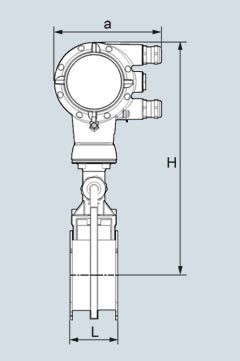
SITRANS FX330 (Vortex), Sandwich version with pressure sensor, front view
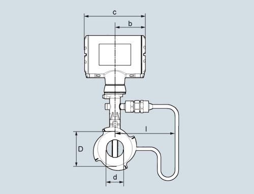
SITRANS FX330 (Vortex), Sandwich version with pressure sensor, side view
Sandwich version EN
Size
Pressure rating
Dimensions [mm (inch)]
Weight [kg (lb)]
DN
PN
a
b
c
d
D
L
H
l
Flowmeter (without pressure sensor)
Flowmeter (with pressure sensor)
15
16 ... 100
133 (5.24)
105 (4.13)
179 (7.05)
16 (0.63)
45 (1.77)
65 (2.56)
265 (10.43)
174.25 (6.86)
3.5 (7.72)
4.1 (9.04)
25
16 ... 100
133 (5.24)
105 (4.13)
179 (7.05)
24 (0.94)
65 (2.56)
65 (2.56)
265 (10.43)
174.25 (6.86)
4.3 (9.48)
4.9 (10.80)
40
16 ... 100
133 (5.24)
105 (4.13)
179 (7.05)
38 (1.50)
82 (3.23)
65 (2.56)
270 (10.63)
174.5 (6.87)
4.9 (10.80)
5.5 (12.13)
50
16 ... 100
133 (5.24)
105 (4.13)
179 (7.05)
50 (1.97)
102 (4.02)
65 (2.56)
275 (10.83)
174.5 (6.87)
6 (13.23)
6.6 (14.55)
80
16 ... 100
133 (5.24)
105 (4.13)
179 (7.05)
74 (2.91)
135 (5.31)
65 (2.56)
290 (11.42)
174.25 (6.86)
8.2 (18.08)
8.8 (19.40)
100
16 ... 100
133 (5.24)
105 (4.13)
179 (7.05)
97 (3.82)
158 (6.22)
65 (2.56)
310 (12.20)
176.5 (6.95)
9.5 (20.94)
10.1 (22.27)
Sandwich version ANSI
Size
Pressure rating
Dimensions [inch]
Weight [lb]
DN
Class
a
b
c
d
D
L
H
l
Flowmeter (without pressure sensor)
Flowmeter (with pressure sensor)
½"
150, 300
5.32
4.26
7.25
0.63
1.77
2.56
10.43
6.82
7.72
9.04
½"
600
5.32
4.26
7.25
0.55
1.77
2.56
10.43
6.82
7.72
9.04
1"
150, 300, 600
5.32
4.26
7.25
0.94
2.56
2.56
10.43
6.82
9.48
10.80
1½"
150, 300, 600
5.32
4.26
7.25
1.50
3.23
2.56
10.63
6.82
10.80
12.13
2"
150, 300, 600
5.32
4.26
7.25
1.97
4.02
2.56
10.83
6.82
13.23
14.55
3"
150, 300, 600
5.32
4.26
7.25
2.91
5.31
2.56
11.42
6.82
18.08
19.40
4"
150, 300, 600
5.32
4.26
7.25
3.82
6.22
2.56
12.20
6.82
20.94
22.27
Remote version
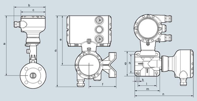
SITRANS FX330 (Vortex), Remote version
Dimension a
Flanged and Sandwich version
Flanged version
DN
15
25
40
50
80
100
150
200
250
300
½"
1"
1½"
2"
3"
4"
6"
8"
10"
12"
[mm]
265.7
265.2
269.2
275.2
287.2
303.7
323.2
348.9
375.7
399.7
[inch]
10.5
10.4
10.6
10.8
11.3
12.0
12.7
13.7
14.8
15.7
Dimension a F1/2R
Flanged version
DN
15
25
40
50
80
100
150
200
250
300
½"
1"
1½"
2"
3"
4"
6"
8"
10"
12"
F1R1) [mm]
-
315.7
315.2
319.2
325.2
337.2
353.7
373.2
398.9
425.7
F1R1) [inch]
-
12.4
12.4
12.6
12.8
13.3
13.9
14.7
15.7
16.8
F2R2) [mm]
-
-
315.7
315.2
319.2
325.2
337.2
353.7
373.2
398.9
F2R2) [inch]
-
-
12.4
12.4
12.6
12.8
13.3
13.9
14.7
15.7
Dimension b ... n
b
c
d
e
f
g
h
j
k
l
m
n
[mm]
139
108
276
191
105
97
72
108
9
72
97
226
[inch]
5.46
4.25
10.9
7.53
4.14
3.82
2.84
4.25
0.35
2.84
3.82
8.90
Flow tables
Measuring Range Limits
Size
Qmin
Qmax
Qmin
Qmax
DN to EN 1092-1
DN to NSI B16.5
EN 1092-1 [m3/h]
EN 1092-1 [m3/h]
ANSI B16.5 [m3/h]
ANSI B16.5 [m3/h]
Water
15
½"
0.45
5.07
0.44
4.94
25
1"
0.81
11.40
0.81
11.40
40
1½"
2.04
28.58
2.04
28.58
50
2"
3.53
49.48
3.53
49.48
80
3"
7.74
108.37
7.74
108.37
100
4"
13.30
186.22
13.30
186.21
150
6"
30.13
421.86
30.13
421.86
200
8"
56.60
792.42
56.60
792.42
250
10"
90.48
1 266.8
90.48
1 266.8
300
12"
131.41
1 839.8
131.41
1 839.8
Values based on water at 20 °C (68 °F)
Size
Qmin
Qmax
Qmin
Qmax
DN to EN 1092-1
DN to ANSI B16.5
EN 1092-1 [m3/h]
EN 1092-1 [m3/h]
ANSI B16.5 [m3/h]
ANS B16.5 [m3/h]
Air
15
½"
6.80
25.33
6.72
24.70
25
1"
10.20
81.43
10.20
81.43
40
1½"
25.35
326.63
25.35
326.63
50
2"
43.89
565.49
43.89
565.49
80
3"
96.14
1 238.64
96.14
1 238.6
100
4"
165.19
2 128.27
165.19
2 128.27
150
6"
374.23
4 821.60
374.23
4 821.6
200
8"
702.95
9 056.8
702.95
9 056.8
250
10"
1 123.7
14 478.0
1 123.7
14 478.0
300
12"
1 632.1
21 028.0
1 632.1
21 028.0
Values based on air at 20 °C (68 °F) and 1.013 barabs (14.7 psiabs)
Flow rate limits
Product
Nominal diameters
Minimum flow rates
Maximum flow rates
to EN
to ANSI
[m/s]
[m/s]
Liquids
DN 15 … DN 300
DN ½"…DN 12"
0.5 x (998/ρ)0.51)
7 x (998/ρ)0.47 1)
Gas, steam/vapor
DN 15 … DN 300
DN ½"…DN 12"
6 x (1.29/ρ)0.52)
7 x (998/ρ)0.47 3)
ρ = operating density [kg/m3]
1) Minimum flow rate 0.3 m/s (0.984 ft/s) - maximum flow rate 7 m/s (23 ft/s)
2) Minimum flow rate 2 m/s (6.6 ft/s)
3) Maximum flow rate 80 m/s (262 ft/s); DN 15: 45 m/s (148 ft/s) and DN 25: 70 m/s (230 ft/s)
Measuring range saturated steam: 1 to 7 bar
Overpressure [bar]
1
3.5
5.2
7
Density [kg/m3]
1.13498
2.4258
3.27653
4.16732
Temperature [°C]
120.6
148.2
160.4
170.6
Flow [kg/h]
min.
max.
min.
max.
min.
max.
min.
max.
DN to EN 1092-1
DN to ASME B16.5
15
½"
5.87
28.75
7.68
61.46
8.93
83.01
10.06
105.57
25
1"
11.82
92.42
17.28
197.53
20.09
266.81
22.66
339.35
40
1½"
29.64
370.71
43.33
792.33
50.63
1 070.2
56.80
1 361.2
50
2"
51.31
641.82
75.02
1 371.8
87.19
1 852.8
98.33
2 356.6
80
3"
112.41
1 405.8
164.33
3 004.7
191.00
4 058.4
215.39
5 161.8
100
4"
193.14
2 415.5
282.36
5 162.7
328.16
6 973.3
370.09
8 869.2
150
6"
437.56
5 472.4
639.69
11 696.0
743.45
15 798.0
838.44
20 093.0
200
8"
821.9
10 279.0
1 201.6
21 970.0
1 396.5
29 675.0
1 574.9
37 743.0
250
10"
1 313.9
16 433.0
1 920.9
35 122.0
2 232.5
47 439.0
2 517.7
60 337.0
300
12"
1 908.3
23 866.0
2 789.8
51 010.0
3 242.4
68 899.0
3 656.6
87 630.0
Measuring range saturated steam: 10.5 to 20 bar
Overpressure [bar]
10.5
14.0
17.5
20.0
Density [kg/m3]
5.88803
7.60297
9.31702
10.5442
Temperature [°C]
186.2
198.5
208.7
215.0
Flow [kg/h]
min.
max.
min.
max.
min.
max.
min.
max.
DN to EN 1092-1
DN to ANSI B16.5
15
½"
12.78
149.17
16.51
192.61
20.23
236.04
22.89
267.12
25
1"
26.93
479.46
30.60
619.11
33.87
758.69
36.04
858.62
40
1½"
67.51
1 878.2
76.72
2 150.7
84.93
2 395.3
90.35
2 557.7
50
2"
116.89
3 251.7
132.82
3 723.4
147.03
4 147.0
156.42
4 428.1
80
3"
256.03
7 122.4
290.93
8 155.8
322.06
9 083.7
342.62
9 699.3
100
4"
439.91
12 238
499.90
14 013.0
553.38
15 608.0
588.69
16 666.0
150
6"
996.62
27 725.0
1 132.5
31 747.0
1 253.7
35 359.0
1 333.7
37 756.0
200
8"
1 872.1
52 079.0
2 127.3
59 634.0
2 354.9
66 419.0
2 505.2
70 921.0
250
10"
2 992.7
83 254.0
3 400.7
95 333.0
3 764.6
106 180.0
4 004.9
113 380.0
300
12"
4 346.5
120 920.0
4 939.1
138 460.0
5 467.5
154 210.0
5 816.5
164 660.0
Measuring range saturated steam: 15 to 100 psig
Overpressure [psig]
15
50
75
100
Density [lbs/ft3]
0.0719
0.1497
0.2036
0.2569
Temperature [°F]
249.98
297.86
320.36
338.184
Flow [lbs/h]
min.
max.
min.
max.
min.
max.
min.
max.
DN to EN 1092-1
DN to ANSI B16.5
15
½"
12.95
64.35
16.83
133.87
19.62
182.02
22.04
229.63
25
1"
26.25
206.83
37.86
430.30
44.15
585.06
49.59
738.09
40
1½"
65.81
829.61
94.92
1 726
110.68
2 346.7
124.32
2 960.5
50
2"
113.94
1 436.3
164.34
2 988
191.63
4 062.9
215.23
5 125.6
80
3"
249.57
3 146.1
360.00
6 545.3
419.74
8 899.4
471.45
11 227
100
4"
428.81
5 405.7
618.51
11 246
721.21
15 291
810.06
19 291
150
6"
971.47
12 246
1 401.2
25 478
1 633.9
34 642
1 835.2
43 703
200
8"
1 824.8
23 004
2 632.1
47 859
3 069.1
65 072
3 447.2
82 092
250
10"
2 917.2
36 774
4 207.7
76 508
4 906.4
104 030
5 510.8
131 230
300
12"
4 236.8
53 410
6 111.1
111 120
7 125.8
151 080
8 003.6
190 600
Measuring range saturated steam: 150 to 300 psig
Overpressure [psig]
150
200
250
300
Density [lbs/ft3]
0.3627
0.4681
0.5735
0.6792
Temperature [°F]
366.08
388.04
406.22
422.06
Flow [lbs/h]
min.
max.
min.
max.
min.
max.
min.
max.
DN to EN 1092-1
DN to ANSI B16.5
15
½"
27.79
324.21
35.86
418.47
43.94
512.66
52.04
607.12
25
1"
58.93
1 042.1
66.94
1 345.1
74.10
1 647.8
80.63
1 951.5
40
1½"
147.72
4 107.2
167.83
4 702.8
185.76
5 237
202.15
5 728
50
2"
255.75
7 111.9
290.56
8 141.9
321.60
9 066.8
350.00
9 917
80
3"
560.19
15 578
636.44
17 834
704.43
19 860
766.60
21 722
100
4"
962.54
26 766
1 093.5
30 643
1 210.4
34 124
1 317.2
37 324
150
6"
2 180.6
60 639
2 477.4
69 421
2 742.1
77 307
2 984
84 556
200
8"
4 096.1
113 900
4 653.6
130 400
5 150.7
145 210
5 605.2
158 830
250
10"
6 548.1
182 090
7 439.3
208 460
8 234.1
232 140
8 960.6
253 910
300
12"
9 510.2
264 460
10 805
302 760
11 959
337 150
13 014
368 770
Особенности
- Integrated pressure and temperature compensation
- Temperature compensation for saturated steam included as standard
- High measuring accuracy
- Maintenance-free sensor
- Non-wearing, fully welded stainless steel construction with high resistance to corrosion, pressure and temperature
- SIL2 certified according to IEC 61508 Edition 2
- Use in hazardous areas
- Integrated reduction of nominal diameter for space-saving and economic installation and large measuring ranges
- Redundant data management: Easy exchange of electronics without loss of calibration and configuration data
- FAD (Free Air Delivery) functionality
- Gross and net heat calculation to support advanced energy management
- Remote version with cable length up to 50 m (164 ft)
Even the basic version of the vortex flowmeter SITRANS FX330 is equipped with temperature compensation for saturated steam applications. With the optional pressure sensor the SITRANS FX330 has integrated density compensation for calculation of corrected volume and mass (online density compensation). The density compensation for calculation of corrected volume and mass is based on the standards of NIST for gases and IAPWS for steam.
Higher measuring accuracy with the use of compact measuring systems
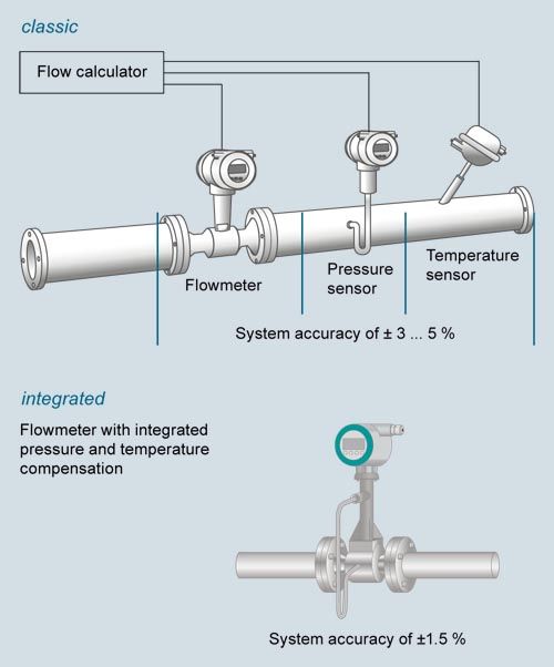
With the classic installation of a vortex flowmeter and separate pressure and temperature sensor as well as flow calculator, all errors occurring in the measuring chain must be taken into account when determining system accuracy. This can result in a measuring error between ± 3 to 5 %.
Using a vortex flowmeter with integrated pressure and temperature compensation such as the SITRANS FX330 allows you not only to lower installation costs but also increase the measuring accuracy of the measuring point. In this case the accuracy is ± 1.5 % of the measured value.
The SITRANS FX330 in flange design is available with integrated reduction of nominal diameter for space-saving installations and large measuring spans. About 90% of all vortex flowmeters are ordered one size smaller than the line diameter in order to increase the flow speed and to get a wider measuring range. Here, the line has to be reduced before and widened after the sensor, typically including 20x DN inlet and 5x DN outlet run. With the reduction and widening of nominal diameter included in the sensor, it is no longer necessary. To compensate the non-existent straight inlet run between reduction and the vortex bluff body, these devices are specially calibrated and linearized.
A new feature of the SITRANS FX330 is the advanced signal processing and filtering called AVFD (Advanced Vortex Frequency Detection): Interferences and disturbances in the measuring signal are suppressed, signals outside from the relevant frequency band are filtered out.
Redundant data management prevents loss of calibration and configuration data when changing electronics or display.
By default, all SITRANS FX330 meters are factory-calibrated (traceable to international standards) and pre-set according to customer specifications. The SITRANS FX330 also comes with an installation wizard to ease installation; e.g. in a steam application it will only show related settings.
Developed according to the standard IEC 61508 edition 2, the SITRANS FX330 can be used in safety-related application with classification SIL2 for continuous volume flow measurement.
Технические данные
SITRANS FX330
Range of application
Flow measurement of liquids, gases and vapors
Mode of operation
Measuring principle
Karman vortex street
Primary measured value
- Volume flow
- Mass flow
- Corrected colume flow
- Density
- Temperature
- Pressure
- Heat energy
Design
Transmitter
- Compact and remote version
Cable length up to 50 m (164 ft)
Sensor
Flange version
Sandwich version
- Integrated temperature measurement
●
●
- Reduction of nominal diameter
●
- Pressure and temperature compensation
●
●
- Isolation valve
●
- Dual measuring device
●1)
●
1) Only available as PVR (product variant request - special request)
Display
4-line graphical display (backlit) with control keys
Operation
- Via local display (languages: German, English, French)
- Via SIMATIC PDM
Accuracy
Volume flow
- Liquids
- Re ≥ 20 000
± 0.75 % of measured value
- 10 000 < Re < 20 000
± 2.0 % of measured value
- Gases and vapors
- Re ≥ 20 000
± 1.0 % of measured value
- 10 000 < Re < 20 000
± 2.0 % of measured value
Mass flow/Corrected volume flow
- Gases and vapors
- Re ≥ 20 000
± 1.5 % of measured value
- 10 000 < Re < 20 000
± 2.5 % of measured value
Mass flow
- Liquid/water
- Re ≥ 20 000
± 1.5 % of measured value
- 10 000 < Re < 20 000
± 2.5 % of measured value
Repeatability (Volume flow)
± 0.1 % of measured value
Operating conditions
Temperature ratings
- Medium
-40 … +240 °C (-40 … +465 °F)
- Ambient
- Non-Ex
-40 … +85 °C (-40… +185 °F)
- Ex
-40 … +65 °C (-40… +140 °F)
- Storage
-50 … +85 °C (-58… +185 °F)
Pressure ratings
Max. 100 bar (1450 psi), higher pressure rates on request
Max. allowable test pressure
• With integrated pressure sensor and isolation valve (closed)
1.5 x PN
• With integrated pressure sensor and without isolation valve
2 times the measuring range of pressure sensor
Process medium
- Density
Taken into consideration when sizing
- Viscosity
< 10 cP
- Reynold's number
> 10000
Recommended flow velocities
- Liquids
0.25 ... 7 m/s (0.82 ... 23 ft/s)
- Gases and vapors
DN 15:
DN25:
2.0 ... 80 m/s (6.6 ... 262.5 ft/s)
3.0 ... 45 m/s (9.8 ... 148 ft/s)
2.0 ... 70 m/s (6.6 ... 230 ft/s)For detailed information see operating instructions "Intended use"
Installation conditions
Inlet run
- For undisturbed flow profile, after pipe section with reducer, after 1 x 90° pipe bend
≥ 15 x DN
- After 2 x 90° pipe bend
≥ 30 x DN
- After 2 x 90° three-dimensional pipe bend
≥ 40 x DN
- After control valves
≥ 50 x DN
- Before flow conditioner
≥ 2 x DN
- After flow conditioner
≥ 8 x DN
Outlet run
≥ 5 x DN
Material
Sensor and process connetions
- Standard
1.4404/316L
- Option
Hastelloy C22 on request
Transmitter housing
Aluminum
- Standard
Aluminum die-cast, two-layer coating (epoxy/polyester)
- Option
Die-cast aluminum with finish for advanced requirements
Pressure sensor gasket
- Standard
FPM
- Option
FFKM
Sensor gasket (Pick-up)
- Standard
1.4535/316L
- Option
Hastelloy C276
Process connections
DIN EN 1092-1
DN 15 ... DN 300/PN 16 ... PN 100
ANSI B16.5
½" ... 12"/150 ... 600 lb
For valid combinations of connection size and pressure rating see table "Sensor variants"
Enclosure rating
Standard
Compact and remote version: IP66/IP67
Option
Remote version: IP66/IP68 for sensor
Power supply
Non-Ex version
14 … 36 V DC
Ex version
14 … 30 V DC
Inputs/Outputs
Current output
4 ... 20 mA, HART
Binary output
Pulse/Frequency/Status/Limit switch
Current input
4 ... 20 mA, passive
Communication
HART 7
Calibration
Standard calibration
3-point calibration:
3 x 15 %, 3 x 50 %, 3 x 80 %Special calibration
5-point calibration:
3 x 15 %, 3 x 30 %, 3 x 50 %, 3 x 60 %, 3 x 80 %Certificates and approvals
Ex approvals
ATEX, QPS, IECEx
CE declaration of conformity
PED 2014/68/EU EMC 2014/30/EU
Safety integration level (SIL)
SIL2 according to IEC 61508