
- Каталог оборудования Siemens
- Каталог продуктов Siemens Industry
- Приводная техника
- Преобразователи
- Стандартные преобразователи
- Общая информация о базовых преобразователях SINAMICS V
- Преобразователи частоты общего назначения SINAMICS G
- Высокопроизводительные преобразователи SINAMICS S
- MICROMASTER
- SIPLUS POSMO A
- SIMODRIVE POSMO
- LOHER DYNAVERT Drive System
- Преобразователи на среднее напряжение
- Преобразователи постоянного тока
- Стандартные преобразователи
- Двигатели переменного тока
- Generators
- Мотор-редукторы
- Flender Gear Units
- Couplings
- Инструментальное программное обеспечение
- Дополнительные компоненты
- Преобразователи
- Техника автоматизации
- Energy
- Автоматизация и безопасность зданий
- Низковольтная коммутационная техника
- Технология безопасности
- Системные решения и продукты для отраслей
- Сервис
- Приводная техника
Cable cross-sections and connections
- Информационные материалы
Информационные материалы
The following tables list the recommended and maximum connectable line and motor-side cable cross sections and connections for a single connection.
The recommended cross-sections are based on the specified fuses. They are valid for a 3-conductor copper cable routed horizontally in air with PVC insulation and a permissible conductor temperature of 70 °C (e.g. Protodur NYY or NYCWY) at an ambient temperature of 40 °C and individual routing.
In conditions (cable routing, cable bundling, ambient temperature) that deviate from this the corresponding correction factors according to IEC 60364‑5‑52 must be considered.For additional information, please refer to the SINAMICS Low Voltage Engineering Manual.
Type rating at 400 V or 690 V
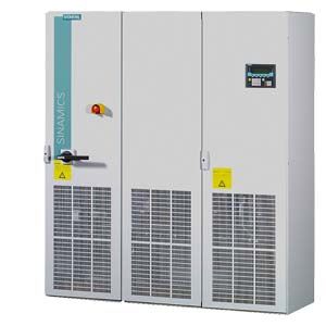
SINAMICS S150 converter cabinet unit
Line supply connection
Motor connection
Cabinet grounding
Recommended cross-section 1)
Maximum conductor cross-section
M12 fixing screw
Recommended cross-section 1)
Maximum conductor cross-section
M12 fixing screw
M12 fixing screw
Remarks
IEC
IEC
(Number of holes)
IEC
IEC
(Number of holes)
(Number of holes)
kW
6SL3710-...
mm2
mm2
mm2
mm2
380 ... 480 V 3 AC
110
7LE32-1AA3
2 × 70
4 × 240
(2)
2 × 50
2 × 150
(2)
(2)
132
7LE32-6AA3
2 × 95
4 × 240
(2)
2 × 70
2 × 150
(2)
(2)
160
7LE33-1AA3
2 × 120
4 × 240
(2)
2 × 95
2 × 150
(2)
(2)
200
7LE33-8AA3
2 × 120
4 × 240
(2)
2 × 95
2 × 150
(2)
(2)
250
7LE35-0AA3
2 × 185
4 × 240
(2)
2 × 150
2 × 240
(2)
(2)
315
7LE36-1AA3
2 × 240
4 × 240
(2)
2 × 185
4 × 240
(2)
(2)
400
7LE37-5AA3
3 × 185
4 × 240
(2)
2 × 240
4 × 240
(2)
(10)
Cu bar
450
7LE38-4AA3
4 × 150
8 × 240
(4)
3 × 185
4 × 240
(2)
(16)
Cu bar
560
7LE41-0AA3
4 × 185
8 × 240
(4)
4 × 185
6 × 240
(3)
(18)
Cu bar
710
7LE41-2AA3
4 × 240
8 × 240
(4)
4 × 240
6 × 240
(3)
(18)
Cu bar
800
7LE41-4AA3
6 × 185
8 × 240
(4)
6 × 185
6 × 240
(3)
(18)
Cu bar
500 … 690 V 3 AC
75
7LG28‑5AA3
50
4 × 240
(2)
35
2 × 70
(2)
(2)
90
7LG31-0AA3
50
4 × 240
(2)
50
2 × 150
(2)
(2)
110
7LG31-2AA3
70
4 × 240
(2)
70
2 × 150
(2)
(2)
132
7LG31-5AA3
95
4 × 240
(2)
70
2 × 150
(2)
(2)
160
7LG31-8AA3
120
4 × 240
(2)
95
2 × 150
(2)
(2)
200
7LG32-2AA3
2 × 70
4 × 240
(2)
120
2 × 150
(2)
(2)
250
7LG32-6AA3
2 × 95
4 × 240
(2)
2 × 70
2 × 185
(2)
(2)
315
7LG33-3AA3
2 × 120
4 × 240
(2)
2 × 95
2 × 240
(2)
(2)
400
7LG34-1AA3
2 × 185
4 × 240
(2)
2 × 120
4 × 240
(2)
(2)
450
7LG34-7AA3
2 × 185
4 × 240
(2)
2 × 150
4 × 240
(2)
(2)
560
7LG35-8AA3
2 × 240
4 × 240
(2)
2 × 185
4 × 240
(2)
(2)
710
7LG37-4AA3
3 × 185
8 × 240
(4)
3 × 150
6 × 240
(3)
(18)
Cu bar
800
7LG38-1AA3
4 × 150
8 × 240
(4)
3 × 185
6 × 240
(3)
(18)
Cu bar
900
7LG38-8AA3
4 × 150
8 × 240
(4)
4 × 150
6 × 240
(3)
(18)
Cu bar
1000
7LG41-0AA3
4 × 185
8 × 240
(4)
4 × 185
6 × 240
(3)
(18)
Cu bar
1200
7LG41-3AA3
4 × 240
8 × 240
(4)
4 × 240
6 × 240
(3)
(18)
Cu bar
1) The recommendations for the North American market in AWG or MCM must be taken from the appropriate NEC (National Electrical Code) and CEC (Canadian Electrical Code) standards.
Cable cross-sections for line and motor connection
It is generally recommended to use shielded 3-conductor three-phase cables between the converter and motor – and for higher power ratings, symmetrical cables where possible. If required, several of these cables can be connected in parallel. There are two main reasons for this:
- Only then can the high IP55 degree of protection at the motor terminal box be easily achieved. The reason for this is that cables are routed into the terminal box through glands, and the number of possible glands is restricted by the terminal box geometry. Therefore single cables are less suitable.
- With symmetrical 3-wire three-phase cables, the summed ampere-turns over the cable outer diameter are equal to zero. They can easily be routed in conductive, metal cable ducts or racks without any significant currents (ground current or leakage current) being induced in these conductive, metal connections. The danger of induced leakage currents and thus of increased cable sheath losses is significantly higher with single-conductor cables.
The cable cross-section required depends on the current being conducted in the cable. The permissible current load capability of cables is defined, for example in IEC 60364‑5‑52. It depends partly on the ambient conditions such as temperature, but also on the routing method. It should be taken into account whether cables are individually routed with relatively good cooling, or whether several cables are routed together; in this case, cable ventilation is significantly poorer, which can therefore result in higher cable temperatures. Regarding this topic, reference is made to the corresponding correction factors for these secondary conditions in IEC 60364‑5‑52.
For 3-conductor copper and aluminum cables with PVC insulation and a permissible conductor temperature of 70 °C (e.g. Protodur NYY or NYCWY), as well as an ambient temperature of 40 °C, the cross-sections can be determined from the following table, which is based on IEC 60364‑5‑52.
Cross-section of 3-conductor cable
Copper cable
Aluminum cable
Individual routing
Several cables next to one another 1)
Individual routing
Several cables next to one another 1)
mm2
A
A
A
A
3 × 2.5
22
17
17
13
3 × 4.0
30
23
23
18
3 × 6.0
37
29
29
22
3 × 10
52
41
40
31
3 × 16
70
54
53
41
3 × 25
88
69
68
53
3 × 35
110
86
84
65
3 × 50
133
104
102
79
3 × 70
171
133
131
102
3 × 95
207
162
159
124
3 × 120
240
187
184
144
3 × 150
278
216
213
166
3 × 185
317
247
244
190
3 × 240
374
292
287
224
Current-carrying capacity according to IEC 60364‑5‑52 at 40 °C
1)A maximum of 9 cables may be routed directly next to one another horizontally on a cable tray.
Cables must be connected in parallel for higher currents.
Note:
The recommendations for the North American market in AWG or MCM must be taken from the appropriate NEC (National Electrical Code) and CEC (Canadian Electrical Code) standards.
Grounding and protective conductor cross-section
The protective conductor must be dimensioned taking into account the following data:
- In the case of a ground fault, no impermissibly high contact voltages resulting from voltage drops on the PE conductor caused by the ground fault current may occur (< 50 V AC or < 120 V DC, IEC 61800‑5‑1, IEC 60364, IEC 60543).
- The protective conductor must not be excessively loaded by any ground fault current it carries.
- If it is possible for continuous currents to flow through the protective conductor when a fault occurs, then the protective conductor cross-section must be dimensioned for this continuous current.
- The protective conductor cross-section must be selected according to EN 60204‑1, EN 60439‑1, IEC 60364.
Cross-section, line conductor
Minimum cross-section, external protective conductor
mm2
mm2
up to 16
Minimum cross-section of line conductor
16 ... 35
16
from 35
Minimum half the cross-section of line conductor
Note:
The recommendations for the North American market in AWG or MCM must be taken from the appropriate NEC (National Electrical Code) and CEC (Canadian Electrical Code) standards.
- Switchgear and motors are usually grounded separately via a local grounding electrode. With this constellation, the ground fault current flows via the parallel ground connections and is divided. In spite of the relatively small protective conductor cross sections used in accordance with the table above, no inadmissible touch voltages occur with this grounding system.
However, from experience gained with different grounding constellations, we recommend that the ground cable from the motor return directly to the converter. For EMC reasons and to avoid bearing currents, for large power ratings, it is preferable to use symmetrical 3-conductor, three-phase cables instead of four-conductor cables. For 3-conductor cables, the protective or PE conductor must be routed separately or arranged symmetrically in the motor cable. Symmetry of the PE conductor is achieved using a conductor surrounding all phase conductors or using a cable with a symmetrical arrangement of the three phase conductors and three ground conductors.
For additional information, please refer to the SINAMICS Low Voltage Engineering Manual. - Through their high-speed control, the converters limit the load current (motor and ground fault currents) to an rms value corresponding to the rated current. As a result of this fact, we recommend that the cross-section of the protective conductor to ground the cabinets is the same as for the outer (main) conductor.