
- Каталог оборудования Siemens
- Каталог продуктов Siemens Industry
- Приводная техника
- Преобразователи
- Стандартные преобразователи
- Общая информация о базовых преобразователях SINAMICS V
- Преобразователи частоты общего назначения SINAMICS G
- Высокопроизводительные преобразователи SINAMICS S
- MICROMASTER
- SIPLUS POSMO A
- SIMODRIVE POSMO
- LOHER DYNAVERT Drive System
- Преобразователи на среднее напряжение
- Преобразователи постоянного тока
- Стандартные преобразователи
- Двигатели переменного тока
- Generators
- Мотор-редукторы
- Flender Gear Units
- Couplings
- Инструментальное программное обеспечение
- Дополнительные компоненты
- Преобразователи
- Техника автоматизации
- Energy
- Автоматизация и безопасность зданий
- Низковольтная коммутационная техника
- Технология безопасности
- Системные решения и продукты для отраслей
- Сервис
- Приводная техника
Converter cabinet units
- Заказные данные (27)
- Информационные материалы
Область применения
SINAMICS S150 is especially suitable for use in all applications that place the highest demands on process operations with dynamic, reproducible processes. These include, for example:
- Test stands
- Centrifuges
- Elevators and cranes
- Cross cutters and shears
- Conveyor belts with a high power demand and energy recovery
- Presses
- Cable winches
Дизайн
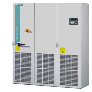
The SINAMICS S150 converter cabinet units are characterized by their compact, modular and service-friendly design.
Design example of a SINAMICS S150 converter cabinet unit
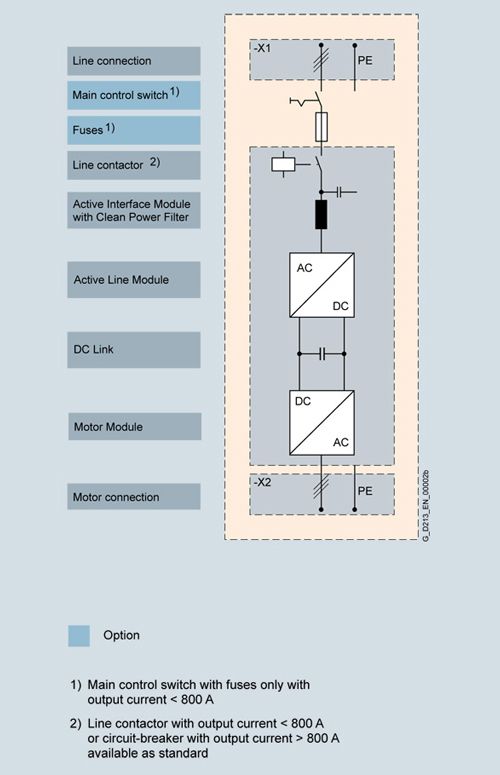
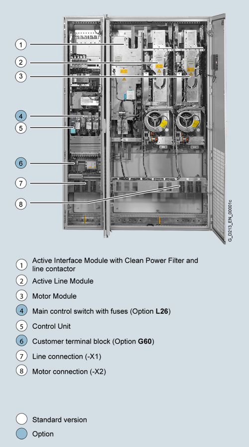
Basic design of a SINAMICS S150 converter cabinet unit with a number of version-specific options
Coated modules
The following devices are equipped as standard with coated modules:
- Chassis format units
- Control Units
- Sensor Modules
- Terminal Modules
- Advanced Operator Panel (AOP30)
The coating on the modules protects the sensitive SMD components against corrosive gases, chemically active dust and moisture.
Nickel-plated busbars
All of the copper busbars used in the converter cabinets are nickel-plated in order to achieve the best possible immunity to environmental effects. Further, it is possible to eliminate having to clean the contacts at the customer connections, which is required for bare copper connections.
Note:
With some options, parts of the copper busbars cannot be nickel-plated for technical reasons.
Degrees of protection
The EN 60529 standard covers the protection of electrical equipment by means of housings, covers or equivalent, and includes:
- Protection of persons against accidental contact with live or moving parts within the housing and protection of the equipment against the ingress of solid foreign bodies (touch protection and protection against ingress of solid foreign bodies)
- Protection of the equipment against the ingress of water (water protection)
- Abbreviations for the internationally agreed degrees of protection
The degrees of protection are specified by abbreviations comprising the code letters IP and two digits.
Degree of protection
First digit
(Touch protection and protection against foreign bodies)
Second digit
(Protection of equipment against the ingress of water)
IP20
(Standard)
Protected against solid foreign bodies
with a diameter ≥ 12.5 mmNo water protection
IP21
(Option M21)
Protected against solid foreign bodies
with a diameter ≥ 12.5 mmProtected against drip water
Vertically falling water drops must not have any harmful effects.
IP23
(Option M23)
Protected against solid foreign bodies
with a diameter ≥ 12.5 mmProtected against spray water
Water sprayed on both sides of the vertical at an angle of up to 60° shall not have a harmful effect.
IP43
(Option M43)
Protected against solid foreign bodies
diameter ≥ 1 mmProtected against spray water
Water sprayed on both sides of the vertical at an angle of up to 60° shall not have a harmful effect.
IP54
(Option M54)
Dust protected
Ingress of dust is not totally prevented, but dust must not be allowed to enter in such quantities that the functioning or safety of the equipment is impaired.
Protected against splash water
Water splashing onto the housing from any direction must not have any harmful effects.
Характеристика
Derating data
SINAMICS S150 converter cabinet units and the associated system components are rated for an ambient temperature of 40 °C and installation altitudes up to 2000 m above sea level.
At ambient temperatures > 40 °C, the output current must be reduced. Ambient temperatures above 50 °C are not permissible.
At installation altitudes > 2000 m above sea level, it must be taken into account that the air pressure, and therefore air density, decreases as the height increases. As a consequence, the cooling efficiency and the insulation capacity of the air also decrease.
Due to the reduced cooling efficiency, it is necessary, on the one hand, to reduce the ambient temperature and on the other hand, to lower heat loss in the converter cabinet unit by reducing the output current, whereby ambient temperatures lower than 40 °C may be offset to compensate.
The following table lists the permissible output currents depending on the installation altitude and ambient temperature for the various degrees of protection. The specified values already include a permitted compensation in respect of installation altitude and ambient temperatures < 40 °C (temperature at the air intake of the converter cabinet unit).
The values apply under the precondition that the cooling air flow stated in the technical specifications is ensured by the way the devices are installed in the cabinet.
As additional measure for installation altitudes from 2000 m up to 5000 m, an isolating transformer is required in order to reduce transient overvoltages according to EN 60664‑1. For additional information, please refer to the SINAMICS Low Voltage Engineering Manual.
Current-derating factors for converter cabinet units depending on the ambient / air intake temperature, the installation altitude and the degree of protection
Degree of protection
Installation altitude above sea level
Current derating factor (as a percentage of the rated current)
for an ambient / air intake temperature ofm
20 °C
25 °C
30 °C
35 °C
40 °C
45 °C
50 °C
IP20, IP21, IP23, IP43
0 ... 2000
100 %
100 %
100 %
100 %
100 %
93.3 %
86.7 %
2001 ... 2500
100 %
100 %
100 %
100 %
96.3 %
2501 ... 3000
100 %
100 %
100 %
98.7 %
3001 ... 3500
100 %
100 %
100 %
3501 ... 4000
100 %
100 %
96.3 %
4001 ... 4500
100 %
97.5 %
4501 ... 5000
98.2 %
IP54
0 ... 2000
100 %
100 %
100 %
100 %
93.3 %
86.7 %
80.0 %
2001 ... 2500
100 %
100 %
100 %
96.3 %
89.8 %
2501 ... 3000
100 %
100 %
98.7 %
92.5 %
3001 ... 3500
100 %
100 %
94.7 %
3501 ... 4000
100 %
96.3 %
90.7 %
4001 ... 4500
97.5 %
92.1 %
4501 ... 5000
93.0 %
Current derating depending on the pulse frequency
To reduce motor noise or to increase output frequency, the pulse frequency can be increased relative to the factory setting (1.25 kHz or 2 kHz). When the pulse frequency is increased, the derating factor of the output current must be taken into account. This derating factor must be applied to the currents specified in the technical specifications.
For additional information, please refer to the SINAMICS Low Voltage Engineering Manual.
Derating factor of the output current depending on the pulse frequency for devices with a rated pulse frequency of 2 kHz
SINAMICS S150 converter cabinet unit
Type rating
at 400 VOutput current
at 2 kHzDerating factor
at the pulse frequency
6SL3710-...
kW
A
2.5 kHz
4 kHz
5 kHz
7.5 kHz
8 kHz
380 ... 480 V 3 AC
7LE32-1AA3
110
210
95 %
82 %
74 %
54 %
50 %
7LE32-6AA3
132
260
95 %
83 %
74 %
54 %
50 %
7LE33-1AA3
160
310
97 %
88 %
78 %
54 %
50 %
7LE33-8AA3
200
380
96 %
87 %
77 %
54 %
50 %
7LE35-0AA3
250
490
94 %
78 %
71 %
53 %
50 %
Derating factor of the output current depending on the pulse frequency for devices with a rated pulse frequency of 1.25 kHz
SINAMICS S150 converter cabinet unit
Type rating
at 400 V or 690 VOutput current
at 1.25 kHzDerating factor
at the pulse frequency
6SL3710-...
kW
A
2 kHz
2.5 kHz
4 kHz
5 kHz
7.5 kHz
380 ... 480 V 3 AC
7LE36-1AA3
315
605
83 %
72 %
64 %
60 %
40 %
7LE37-5AA3
400
745
83 %
72 %
64 %
60 %
40 %
7LE38-4AA3
450
840
87 %
79 %
64 %
55 %
40 %
7LE41-0AA3
560
985
92 %
87 %
70 %
60 %
50 %
7LE41-2AA3
710
1260
92 %
87 %
70 %
60 %
50 %
7LE41-4AA3
800
1405
97 %
95 %
74 %
60 %
50 %
500 ... 690 V 3 AC
7LG28-5AA3
75
85
93 %
89 %
71 %
60 %
40 %
7LG31-0AA3
90
100
92 %
88 %
71 %
60 %
40 %
7LG31-2AA3
110
120
92 %
88 %
71 %
60 %
40 %
7LG31-5AA3
132
150
90 %
84 %
66 %
55 %
35 %
7LG31-8AA3
160
175
92 %
87 %
70 %
60 %
40 %
7LG32-2AA3
200
215
92 %
87 %
70 %
60 %
40 %
7LG32-6AA3
250
260
92 %
88 %
71 %
60 %
40 %
7LG33-3AA3
315
330
89 %
82 %
65 %
55 %
40 %
7LG34-1AA3
400
410
89 %
82 %
65 %
55 %
35 %
7LG34-7AA3
450
465
92 %
87 %
67 %
55 %
35 %
7LG35-8AA3
560
575
91 %
85 %
64 %
50 %
35 %
7LG37-4AA3
710
735
87 %
79 %
64 %
55 %
35 %
7LG38-1AA3
800
810
97 %
95 %
71 %
55 %
35 %
7LG38-8AA3
900
910
92 %
87 %
67 %
55 %
33 %
7LG41-0AA3
1000
1025
91 %
86 %
64 %
50 %
30 %
7LG41-3AA3
1200
1270
87 %
79 %
55 %
40 %
25 %
The following table lists the maximum achievable output frequency as a function of the pulse frequency:
Pulse frequency
Max. achievable output frequency
1.25 kHz
100 Hz
2 kHz
160 Hz
2.5 kHz
200 Hz
≥4 kHz
300 Hz
Overload capability
The SINAMICS S150 converter cabinet units are equipped with an overload reserve to deal with breakaway torques, for example. If larger surge loads occur, this must be taken into account in the configuration. For drives with overload requirements, the appropriate base load current must, therefore, be used as a basis for the required load.
The criterion for overload is that the drive is operated with its base load current before and after the overload occurs on the basis of a duty cycle duration of 300 s.
For temporary, periodic duty cycles with high variations of load within the duty cycle, the relevant sections of the SINAMICS Low Voltage Engineering Manual must be observed.
The base-load current for a low overload IL is the basis for a duty cycle of 110 % for 60 s or 150 % for 10 s.

Low overload
The base-load current IH for a high overload is based on a load cycle of 150 % for 60 s or 160 % for 10 s.

High overload
Функции
AOP30 Advanced Operator Panel
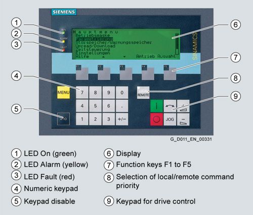
An Advanced Operator Panel (AOP30) is installed in the cabinet door of the converter for operation, monitoring and commissioning tasks.
The user is guided by interactive menus through the drive commissioning screens. When the drive is commissioned for the first time, only 6 motor parameters (which can be found on the motor rating plate) have to be entered on the AOP30. The closed-loop control is then optimized automatically to adapt the converter to the motor.
The AOP30's two-stage safety concept prevents unintentional or unauthorized changes to settings. Operation of the drive from the operator panel can be disabled by the keyboard lock and so that only parameter values and process variables can be displayed on the operator panel. The OFF key is factory-set to "active", but can be deactivated by the customer. A password can be used to prevent the unauthorized changing of converter parameters.
German, English, French, Italian, Spanish and Chinese are stored on the CU320‑2 Control Unit CompactFlash card as operator panel languages. The desired language must be downloaded to the AOP30 prior to commissioning. In addition to these standard operator panel languages, Russian can also be retro-installed. Further languages are available on request.
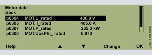
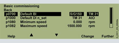
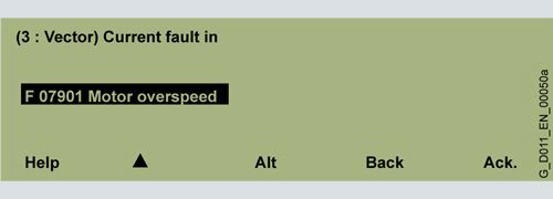
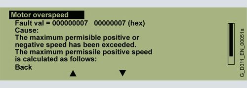
Examples of plain-text displays during various phases of operation are shown below.
The first commissioning is performed via the operator panel.

Only 6 motor parameters have to be entered: Power, speed, current, cos φ, voltage and frequency of the motor.
This information can be found on the motor rating plate, and must be entered in the screens on the display by following a short, menu-assisted procedure. The motor cooling method must also be specified.
The next screen contains the parameter values that are used to automatically optimize the control.
During operation, the display shows current data, such as setpoints and actual values as absolute values or it is possible to parameterize up to 3 process variables as a quasi-analog bar display.


Any alarms that occur are signaled by flashing of the yellow ALARM LED, faults by the red FAULT LED, which is then lit. There is also an indication of the cause displayed in plain text on the display's status line (with counter/remedial measures).
Communication with higher-level controller and customer terminal block
A PROFIBUS or PROFINET interface on the Control Unit CU320-2 is provided as standard as the customer control interface.
This interface can be used to connect the system to the higher-level controller using analog and digital signals, or to connect additional units.
The inputs and outputs available as standard can be optionally expanded by up to two Terminal Modules TM31 (refer to the description of options, option G60 or G61). To simplify configuration and commissioning of the drive, the TM31 Terminal Module can be preset to a variety of factory settings.
For additional information, please refer to the SINAMICS Low Voltage Engineering Manual.
Open-loop and closed-loop control functions
SINAMICS S150 has a high-dynamic vector control with speed and current control – with and without speed actual value feedback.
Software and protective functions
The software functions available as standard are described below:
Software and protective functions
Description
Setpoint input
The setpoint can be specified both internally and externally; internally as a fixed setpoint, motorized potentiometer setpoint or jog setpoint, externally via the communications interface or an analog input. The internal fixed setpoint and the motorized potentiometer setpoint can be switched or adjusted via control commands from any interface.
Motor identification
The automatic motor identification function makes commissioning faster and easier and optimizes closed-loop control of the drive.
Ramp-function generator
A user-friendly ramp-function generator with separately adjustable ramp-up and ramp-down times, together with adjustable rounding times in the lower and upper speed ranges, allows the drive to be smoothly accelerated and braked. This results in a good speed control response and plays its role in reducing the stress on the mechanical system. The down ramps can be parameterized separately for quick stop.
Vdc max controller
The Vdc max controller automatically prevents overvoltages in the DC link, if the set down ramp is too short, for example. This may also extend the set ramp-down time.
Kinetic buffering (KIP)
For brief line supply failures, the kinetic energy of the rotating drive is used to buffer the DC link and therefore prevents fault trips. The drive converter remains operational as long as the drive can provide regenerative energy as a result of its motion and the DC link voltage does not drop below the shutdown threshold. When the line supply recovers within this time, the drive is again bumplessly accelerated up to its setpoint speed.
Automatic restart
The automatic restart switches the drive on again when the power is restored after a power failure, and ramps up to the current speed setpoint.
Flying restart
The flying restart function allows the converter to be switched to a motor that is still turning. With the voltage sensing capability provided by the optional VSM10, the flying restart time for large induction motors can be significantly reduced because the motor does not need to be de-magnetized.
Technology controller
The technology controller function module allows simple control functions to be implemented, e.g. level control or volumetric flow control and complex tension controls. The existing D component can act both on the system deviation well as on the actual value (factory setting). The P, I, and D components are set separately.
Free function blocks
Using the freely programmable function blocks, it is easy to implement logic and arithmetic functions for controlling the SINAMICS drive. The blocks can be programmed at the operator panel or the STARTER commissioning tool.
SINAMICS Drive Control Chart (SINAMICS DCC)
SINAMICS DCC is an additional tool for the easy configuration of technological functions for SINAMICS. The block library contains a large selection of control, arithmetic and logic blocks as well as extensive open-loop and closed-loop control functions. The user-friendly DCC editor enables easy graphics-based configuration, allows control loop structures to be clearly represented and provides a high degree of reusability of charts that have already been created. SINAMICS DCC is an add-on to the STARTER commissioning tool (→ Tools and Engineering).
I2t sensing for motor protection
A motor model stored in the converter software calculates the motor temperature based on the current speed and load. More exact measurement of the temperature, which also takes into account the influence of the ambient temperature, is possible by means of direct temperature measurement using KTY84 sensors in the motor winding.
Motor temperature evaluation
Motor protection by evaluating a KTY84, PTC or Pt100 temperature sensor. When a KTY84 temperature sensor is connected, the limit values can be set for alarm or shutdown. When a PTC thermistor is connected, the system reaction to triggering of the thermistor (alarm or trip) can be defined.
Motor blocking protection
A blocked motor is detected and protected against thermal overloading by a fault trip.
Brake control
"Simple brake control" for control of holding brakes:
The holding brake is used to secure drives against unwanted motion when deactivated."Extended brake control" function module for complex brake control, e.g. for motor holding brakes and operational brakes:
When braking with a feedback signal, the brake control reacts to the feedback signal contacts of the brake.Write protection
Write protection to prevent unintentional changing of the setting parameters (without password function).
Know-how protection
Know-how protection for encrypting stored data, e.g. to protect configuration know-how, and to protect against changes and duplication (with password function).
Web server
The integrated web server provides information about the drive unit via its web pages. The web server is accessed using an Internet browser via unsecured (http) or secured transmission (https).
Power unit protection
Power unit protection
Description
Ground fault monitoring at the output
A ground fault at the output is detected by a total current monitor and results in shutdown in grounded systems.
Electronic short-circuit protection at the output
A short-circuit at the output (e.g. at the converter output terminals, in the motor cable or in the motor terminal box) is detected and the converter shuts down with a "fault".
Thermal overload protection
An alarm is issued first when the overtemperature threshold responds. If the temperature continues to rise, the unit either shuts down or independently adjusts the pulse frequency or output current so that thermal load is reduced. Once the cause of the fault has been eliminated (e.g. cooling has been improved), the original operating values are automatically resumed.
Особенности
The self-commutating, pulsed infeed/regenerative unit uses IGBT technology and is equipped with a Clean Power Filter. This combination guarantees extremely line-friendly behavior which is characterized by the following:
- Negligible line harmonics as a result of the innovative Clean Power Filter (<< 1 %)
- The stringent limit values of the standard IEEE 519‑1992 are fully complied with.
- Regenerative feedback (four-quadrant operation)
- Tolerant to fluctuations in the line voltage
- Operation on weak line supplies
- Reactive power compensation is possible (inductive or capacitive)
- High drive dynamic performance
In addition, factors have been considered to ensure easy handling of the drive from the planning and design phase through to operation. These factors include:
- Compact, modular design with an optimum degree of service friendliness
- Straightforward configuring and commissioning thanks to assistance provided by the SIZER for Siemens Drives and STARTER tools
- Simple installation, as it is ready to be connected up
- Fast, menu-prompted commissioning with no complex parameterization
- Clear and convenient drive monitoring/diagnostics, commissioning and operation via a user-friendly graphical operator panel with measured values displayed in plain text or in a quasi-analog bar display.
- SINAMICS as an integral part of Totally Integrated Automation (TIA). The TIA concept offers an optimized range of products for automation and drive technology. This concept is characterized by configuration, communication, and data management that are consistent throughout the product range. SINAMICS is fully integrated in the TIA concept.
Separate S7/PCS7 blocks and faceplates for WinCC are available. - Integration in SIMATIC H systems via a Y link
- SINAMICS Drive Control Chart (SINAMICS DCC)
SINAMICS DCC is an additional tool for the easy configuration of process-oriented functions for SINAMICS. The block library encompasses a large selection of closed-loop, arithmetic and logic blocks, as well as a more comprehensive range of open-loop and closed-loop control functions. The user-friendly DCC editor enables easy graphics-based configuration, allows control loop structures to be clearly represented and provides a high degree of reusability of charts that have already been created. SINAMICS DCC is an add-on to the STARTER commissioning tool.
Опции
When ordering a converter with options, add the suffix "-Z" to the article number and then the order code(s) for the desired option(s).
Example:
6SL3710-7LE32-1AA3-Z
M07+D60+...See also ordering examples.
Available options
Order code
Input side
Use in the first environment according to EN 618003, Category C2 (TN-TT line supplies with grounded neutral point)
L00
Infeed module one level lower
L04
Surge suppression
L21
Main switch incl. fuses or circuit breakers
L26
Line filter monitoring
L40
EMC shielding busbar (cable connection from below) 1)
M70
Output side
dv/dt filter plus Voltage Peak Limiter
L07
Motor reactor
L08
dv/dt filter plus Voltage Peak Limiter
L10
Sine-wave filter (only for the voltage range 380 to 480 V, up to 200 kW)
L15
EMC shielding busbar (cable connection from below) 1)
M70
Motor protection and safety functions
EMERGENCY OFF pushbutton installed in the cabinet door
L45
EMERGENCY OFF category 0, 230 V AC or 24 V DC
L57
EMERGENCY STOP category 1, 230 V AC
L59
EMERGENCY STOP category 1, 24 V DC
L60
Thermistor motor protection (alarm)
L83
Thermistor motor protection (trip)
L84
Pt100 evaluation unit
L86
Insulation monitoring
L87
Additional touch protection
M60
Degree of protection increase
Degree of protection IP21
M21
Degree of protection IP23
M23
Degree of protection IP43
M43
Degree of protection IP54
M54
Mechanical options
Base 100 mm high, RAL 7022
M06
Cable-marshaling compartment 200 mm high, RAL 7035
M07
Line connection from above
M13
Motor connection from above
M78
Crane transport assembly (top-mounted)
M90
Safety Integrated
Safety license for 1 axis
K01
Second SMC30 Sensor Module Cabinet-Mounted
K52
Terminal module for controlling the Safe Torque Off and Safe Stop 1 safety functions
K82
TM54F Terminal Module
K87
Safe Brake Adapter SBA, 230 V AC
K88
Other options
CBC10 Communication Board
G20
CBE20 Communication Board
G33
TM150 temperature sensor evaluation unit
G51
TM31 Terminal Module
G60
Additional TM31 Terminal Module
G61
TB30 Terminal Board
G62
SMC10 Sensor Module Cabinet-Mounted
K46
SMC20 Sensor Module Cabinet-Mounted
K48
SMC30 Sensor Module Cabinet-Mounted
K50
VSM10 Voltage Sensing Module
K51
CU320‑2 PN Control Unit
K95
Connection for external auxiliary equipment
L19
Cabinet lighting with service socket
L50
Cabinet anti-condensation heating
L55
25/125 kW braking unit
for line voltages of 380 … 480 V (110 … 132 kW)
and 660 … 690 V (75 … 132 kW)L61
50/250 kW braking unit
for line voltages of 380 … 480 V (160 … 800 kW)
and 660 … 690 V (160 … 1200 kW)L62
25/125 kW braking unit
for line voltages of 500 … 600 V (110 … 132 kW)L64
50/250 kW braking unit
for line voltages of 500 … 600 V (160 … 1200 kW)L65
Marking of all control cable wire ends
M91
Special cabinet paint finish 2)
Y09
One-line label for system identification, 40 × 80 mm
Y31
Two-line label for system identification, 40 × 180 mm
Y32
Four-line label for system identification, 40 × 180 mm
Y33
Documentation (standard: English/German)
Documentation, production flowchart: one issue
B43
Documentation, production flowchart: updated every two weeks
B44
Documentation, production flowchart: updated every month
B45
Documentation in German
D00
Customer documentation (circuit diagram, terminal diagram, layout diagram) in DXF format
D02
Customer documentation as hard copy
D04
Preliminary version of customer documentation
D14
Documentation in Russian
D56
Documentation in English / French
D58
Documentation in English / Spanish
D60
Documentation in Italian
D72
Documentation in English
D76
Documentation in French
D77
Documentation in Spanish
D78
Documentation in English / Italian
D80
Documentation in Chinese
D84
Documentation in English / Chinese
D91
Documentation in English / Portuguese (Brazil)
D93
Documentation in English / Russian
D94
Rating plate data (standard: English/German)
Rating plate data in English/French
T58
Rating plate data in English/Spanish
T60
Rating plate data in English/Italian
T80
Rating plate data in English/Portuguese (Brazil)
T83
Rating plate data in English/Russian
T85
Rating plate data in English/Chinese
T91
Options specific to the chemical industry
NAMUR terminal block
B00
Protective separation for 24 V supply (PELV)
B02
Outlet for external auxiliary equipment (uncontrolled)
B03
Options specific to the shipbuilding industry
Marine version
M66
Individual certificate from Germanische Lloyd (GL)
E11
Individual certificate from Lloyds Register (LR)
E21
Individual certificate from Bureau Veritas (BV)
E31
Individual certificate from Det Norske Veritas (DNV)
E51
Individual certificate from American Bureau of Shipping (ABS)
E61
Individual certificate from Chinese Certification Society (CCS)
E71
Converter acceptance in presence of customer
Visual acceptance
F03
Function test without motor
F71
Function test with test bay motor under no-load conditions
F75
Insulation test
F77
Customer-specific acceptance inspections (on request)
F97
Converter acceptance without the customer present
Function test without motor
F72
Function test with test bay motor under no-load conditions
F74
Insulation test
F76
1) This option is listed for the input- and output-side options, but is only required once.
2) The order code Y.. requires data in plain text.
Option selection matrix
Certain options can mutually exclude one another
(options that are not involved, are also not shown).✓
Possible combination
–
Combination not possible
Electrical options
L07
L08
L10
L15
L57
L59
L60
L61/L64
L62/L65
L87
K82
M78
L07
–
–
–
✓
✓
✓
✓
✓
✓
✓
–
L08
–
–
–
✓
✓
✓
✓
✓
✓
✓
–
L10
–
–
–
✓
✓
✓
✓
✓
✓
✓
–
L15
–
–
–
✓
✓
✓
✓
✓
✓
✓
–
L57
✓
✓
✓
✓
–
–
✓
✓
✓
✓
✓
L59
✓
✓
✓
✓
–
–
✓
✓
✓
✓
✓
L60
✓
✓
✓
✓
–
–
✓
✓
✓
✓
✓
L61/L64
✓
✓
✓
✓
✓
✓
✓
–
✓
✓
✓
L62/L65
✓
✓
✓
✓
✓
✓
✓
–
✓
✓
✓
L87
✓
✓
✓
✓
✓
✓
✓
✓
✓
– 1)
✓
K82
✓
✓
✓
✓
✓
✓
✓
✓
✓
– 1)
✓
M78
–
–
–
–
✓
✓
✓
✓
✓
✓
✓
1) A combination of L87 and K82 is available on request.
Mechanical/electrical options
M06
M07
M13
M21
M23
M43
M54
M60
M66
M70
M78
M06
–
✓
✓
✓
✓
✓
✓
✓
✓
✓
M07
–
✓
✓
✓
✓
✓
✓
✓
✓
✓
M13
✓
✓
–
✓
✓
✓
✓
✓
– 2)
✓
M21
✓
✓
–
–
–
–
– 3)
–
✓
–
M23
✓
✓
✓
–
–
–
–
–
✓
✓
M43
✓
✓
✓
–
–
–
–
–
✓
✓
M54
✓
✓
✓
–
–
–
–
✓
✓
✓
M60
✓
✓
–
– 3)
–
–
–
✓
✓
–
M66
✓
✓
✓
–
–
–
✓
✓
✓
–
M70
✓
✓
– 2)
✓
✓
✓
✓
✓
✓
– 2)
M78
✓
✓
✓
–
✓
✓
✓
–
–
– 2)
2) If the line connection (option M13) and the motor connection (option M78) are from above, the EMC shield bus is not required in the lower cabinet area.
3) Can only be selected for converters in the voltage range 400 V to 250 kW and 690 V to 315 kW. The M60 option is fitted as standard for higher outputs.
Other options
G20
G33
G62
K46
K48
K50
K51
K52
G20
–
–
✓
✓
✓
✓
✓
G33
–
–
✓
✓
✓
✓
✓
G62
–
–
✓
✓
✓
✓
✓
K46
✓
✓
✓
–
–
–
–
K48
✓
✓
✓
–
–
–
–
K50
✓
✓
✓
–
–
–
✓
K51
✓
✓
✓
–
–
–
–
K52
✓
✓
✓
–
–
✓
–
Documentation
D00
D02
D14
D56
D58
D60
D72
D76
D77
D78
D80
D84
D91
D93
D94
D99
D00
✓
✓
✓
✓
✓
✓
✓
✓
✓
✓
✓
✓
✓
✓
–
D02
✓
✓
✓
✓
✓
✓
✓
✓
✓
✓
✓
✓
✓
✓
–
D14
✓
✓
✓
✓
✓
✓
✓
✓
✓
✓
✓
✓
✓
✓
–
D56
✓
✓
✓
✓
✓
✓
✓
✓
✓
✓
✓
✓
✓
–
–
D58
✓
✓
✓
✓
–
✓
–
–
✓
–
✓
–
–
–
–
D60
✓
✓
✓
✓
–
✓
–
✓
–
–
✓
–
–
–
–
D72
✓
✓
✓
✓
✓
✓
✓
✓
✓
–
✓
✓
✓
✓
–
D76
✓
✓
✓
✓
–
–
✓
✓
✓
–
✓
–
–
–
–
D77
✓
✓
✓
✓
–
✓
✓
✓
✓
✓
✓
✓
✓
✓
–
D78
✓
✓
✓
✓
✓
–
✓
✓
✓
✓
✓
✓
✓
✓
–
D80
✓
✓
✓
✓
–
–
–
–
✓
✓
✓
–
–
–
–
D84
✓
✓
✓
✓
✓
✓
✓
✓
✓
✓
✓
–
✓
✓
–
D91
✓
✓
✓
✓
–
–
✓
–
✓
✓
–
–
–
–
–
D93
✓
✓
✓
✓
–
–
✓
–
✓
✓
–
✓
–
–
–
D94
✓
✓
✓
–
–
–
✓
–
✓
✓
–
✓
–
–
–
D99
–
–
–
–
–
–
–
–
–
–
–
–
–
–
–
Rating plate data
T58
T60
T80
T83
T85
T91
T58
–
–
–
–
–
T60
–
–
–
–
–
T80
–
–
–
–
–
T83
–
–
–
–
–
T85
–
–
–
–
–
T91
–
–
–
–
–
Ordering examples
Example 1
Task:
A drive system is required for a vehicle test stand to perform exhaust gas analysis which can simulate driving profiles and cycles as encountered in everyday traffic situations. This means for the drive system that the dynamometer must be operated both in the motoring as well as regenerating modes.A drive with regenerative feedback into the line supply is required as regenerative operation is the predominant operating mode and dynamic switching operations are required.
The max. regenerative power is 200 kW. The drive converter must have degree of protection IP54 as a result of the environmental conditions. An installation altitude of < 1000 m and 45 °C as the maximum ambient temperature can be assumed. The windings must be equipped with Pt100 resistance thermometers and monitored by the drive converter for alarm and trip. A switch disconnector must be provided to disconnect the converter from the 400 V power supply. In addition, the cabinet is to have a special paint finish in RAL 3002.
Solution:
Taking into account the derating factors for degree of protection IP54 and the increased ambient temperature of 45 °C, a converter with a minimum power rating of 223 kW should be configured.
A converter with a power rating of at least 250 kW and options M54 (degree of protection IP54), L26 (main switch including fuses), L86 (Pt100 evaluation unit) and Y09 (special paint finish) is selected.The ordering data are as follows:
6SL3710-7LE35-0AA3-Z
M54+L26+L86+Y09
Cabinet color RAL 3002Example 2
Task:
A drive system is required for a conveyor belt in a brown-coal open-cast mine that is capable of both motor and generator operation. Since the conveyor belt must be capable of starting after a fault when loaded with bulk material, and it is possible for peak loads to occur where 1.5 times the power is required for up to 60 s, the drive system must be designed according to the overload requirements of such a case. The drive converter is installed in a climate-controlled container as a result of the environmental conditions typical of an open-cast mine. The installation altitude is 320 m above sea level and the maximum ambient temperature in the container is 35 °C. The drive is powered through a converter transformer from the medium-voltage system. The drive is connected to an isolated-neutral system and must have insulation monitoring. A motor with separately-driven fan is selected here as the motor is subject to a high load torque when starting and in the lower range. The fan supply voltage is 690 V and must be drawn from the drive converter.
The required motor power is 420 kW.Solution:
Since the converter is installed in an air-conditioned container, it can be designed with degree of protection IP20. The ambient temperature of 35 °C does not necessitate any additional derating. However, due to the specified overload conditions, the base load current IH (for high overload) must be applied. This results in a power of approx. 520 kW for the drive converter. The converter with article no. 6SL3710-7LG35-8AA3 must be selected.Option L87 (insulation monitoring) must be selected for insulation monitoring.
Option L19 (connection for external auxiliaries) must be selected for the controlled outgoing feeder to power the separately driven fan.
The ordering data are as follows:
6SL3710-7LG35-8AA3-Z
L19+L87Технические данные
The most important directives and standards are listed below. These are used as basis for the SINAMICS S150 converter cabinet units and they must be carefully observed to achieve an EMC-compliant configuration that is safe both functionally and in operation.
European directives
2006/95/EC
Low Voltage Directive:
Directive of the European Parliament and Council of December 12, 2006, on the approximation of the laws of the member states relating to electrical equipment designed for use within certain voltage limits2004/108/EC
EMC Directive:
Directive of the European Parliament and Council of December 15, 2004, which repeals directive 89/336/EEC, on the approximation of laws of the member states relating to electromagnetic compatibility2006/42/EC
Machinery Directive:
Directive of the European Parliament and Council of May 17, 2006, on machinery and amending Directive 95/16/EC (recast).European standards
EN ISO 3744
Acoustics – Determination of the sound power level and sound energy level for noise sources that result from sound pressure measurements – envelope surface procedure of the accuracy class 2 for a largely free sound field over a reflecting plane
EN ISO 13849‑1
Safety of machinery – safety-related parts of control systems;
Part 1: General design guidelines (ISO 13849-1: 2006)EN 60146‑1‑1
Semiconductor converters – General requirements and line-commutated converters
Part 1‑1: Specification of basic requirementsEN 60204‑1
Safety of machinery – Electrical equipment of machines;
Part 1: General requirementsEN 60529
Degrees of protection provided by enclosures (IP code)
EN 61508‑1
Functional safety of electrical/electronic/programmable electronic safety-related systems
Part 1: General requirementsEN 61800‑2
Adjustable speed electrical power drive systems
Part 2: General requirements; rating specifications for low voltage adjustable frequency AC power drive systemsEN 61800‑3
Adjustable speed electrical power drive systems
Part 3: EMC requirements and specific test methodsEN 61800‑5‑1
Adjustable speed electrical power drive systems
Part 5: Safety requirements
Main section 1: Electrical and thermal requirementsEN 61800‑5‑2
Adjustable speed electrical power drive systems
Part 5-2: Safety requirements – Functional safety (IEC 61800‑5‑2: 2007)General technical specifications
Electrical specifications
Line voltages
380 … 480 V 3 AC, ±10 % (-15 % <1 min)
500 … 690 V 3 AC, ±10 % (-15 % <1 min)
Line supply types
Grounded TN/TT systems and non-grounded IT systems
Line frequency
47 ... 63 Hz
Output frequency 1)
0 ... 550 Hz
Line power factor
Adjustable (factory-set to cos φ = 1)
Efficiency
>96 %
Overvoltage category
III to EN 61800‑5‑1
Control method
Vector control with and without encoder or V/f control
Fixed speeds
15 fixed speeds plus 1 minimum speed, parameterizable (in the default setting, 3 fixed setpoints plus 1 minimum speed are selectable using terminal block/PROFIBUS/PROFINET)
Skippable speed ranges
4, parameterizable
Setpoint resolution
0.001 rpm digital (14 bits + sign)
12 bits analogBraking operation
Four-quadrant operation is possible as standard
(optional via a braking unit if braking is required when power fails)Mechanical specifications
Degree of protection
IP20 (higher degrees of protection up to IP54 optional)
Protection class
I acc. to EN 61800‑5‑1
Touch protection
EN 50274 / BGV A3 when used for the intended purpose
Cabinet system
Rittal TS8, doors with double-bit key, three-section base plates for cable entry
Paint finish
RAL 7035 (indoor requirements)
Cooling method
Forced air cooling AF according to EN 60146
Ambient conditions
Storage 2)
Transport 2)
Operation
Ambient temperature
-25 ... +55 °C
-25 ... +70 °C
from -40 °C for 24 hours
0 ... 40 °C
to +50 °C, see derating data
Relative humidity
(condensation not permissible)
5 ... 95%
Class 1K4 acc. to IEC 60721‑3‑1
5 ... 95 % at 40 °C
Class 2K3 acc. to IEC 60721‑3‑2
5 ... 95%
Class 3K3 acc. to IEC 60721‑3‑3
Environmental class/harmful chemical substances
Class 1C2 acc. to IEC 60721‑3‑1
Class 2C2 acc. to IEC 60721‑3‑2
Class 3C2 acc. to IEC 60721‑3‑3
Organic/biological influences
Class 1B1 acc. to IEC 60721‑3‑1
Class 2B1 acc. to IEC 60721‑3‑2
Class 3B1 acc. to IEC 60721‑3‑3
Degree of pollution
2 acc. to EN 61800‑5‑1
Installation altitude
Up to 2000 m above sea level without derating;
> 2000 m see derating dataMechanical stability
Storage 2)
Transport 2)
Operation
Vibratory load
Class 1M2 acc. to IEC 60721‑3‑1
Class 2M2 acc. to IEC 60721‑3‑2
–
- Deflection
1.5 mm at 5 ... 9 Hz 3)
3.1 mm at 5 ... 9 Hz 3)
0.075 mm at 10 ... 58 Hz
- Acceleration
5 m/s² at >9 ... 200 Hz
10 m/s² at 9 ... 200 Hz
9.8 m/s2 at 58 ... 200 Hz
Shock load
Class 1M2 acc. to IEC 60721‑3‑1
Class 2M2 acc. to IEC 60721‑3‑2
Class 3M4 acc. to IEC 60721‑3‑3
- Acceleration
40 m/s² at 22 ms
100 m/s² at 11 ms
100 m/s2 at 11 ms
Compliance with standards
Conformances/approvals, according to
CE (EMC Directive No. 2004/108/EC and Low Voltage Directive No. 2006/95/EC and Machinery Directive No. 2006/42/EC for functional safety)
Radio interference suppression
SINAMICS drive converter systems are not designed for connection to the public grid (first environment). Radio interference suppression is compliant with the EMC product standard for variable-speed drives EN 61800‑3, "Second environment" (industrial networks). EMC disturbances can occur when connected to the public power networks. However, if additional measures are taken (e.g. line filter), it can also be operated in the "first environment".
1)Please note:
- The correlation between the maximum output frequency, pulse frequency and current derating. Higher output frequencies on request.
- The correlation between the maximum output frequency and permissible output current (current derating).
Information is provided in the SINAMICS Low Voltage Configuration Manual.
2) In transport packaging.
Deviations from the specified classes are underlined.
Line voltage 380 ... 480 V 3 AC
SINAMICS S150 Converter Cabinet Units
6SL3710-7LE32-1AA3
6SL3710-7LE32-6AA3
6SL3710-7LE33-1AA3
6SL3710-7LE33-8AA3
6SL3710-7LE35-0AA3
6SL3710-7LE36-1AA3
Type rating
- At IL (50 Hz 400 V) 1)
kW
110
132
160
200
250
315
- At IH (50 Hz 400 V) 1)
kW
90
110
132
160
200
250
- At IL (60 Hz 460 V) 2)
hp
150
200
250
300
400
500
- At IH (60 Hz 460 V) 2)
hp
150
200
200
250
350
350
Output current
- Rated current Irated O
A
210
260
310
380
490
605
- Base-load current IL 3)
A
205
250
302
370
477
590
- Base-load current IH 4)
A
178
233
277
340
438
460
- Maximum current Imax O
A
307
375
453
555
715
885
Infeed/regenerative feedback current
- Rated input current Irated I
A
197
242
286
349
447
549
- Maximum input current Imax I
A
315
390
570
570
735
907
Current demand, max. 5)
- 24 V DC aux. power supply
A
Internal
Internal
Internal
Internal
Internal
Internal
Pulse frequency 6)
- Rated frequency
kHz
2
2
2
2
2
1.25
- Pulse frequency, max.
- Without current derating
kHz
2
2
2
2
2
1.25
- With current derating
kHz
8
8
8
8
8
7.5
Power loss, max. 7)
- At 50 Hz 400 V
kW
6.31
7.55
10.01
10.72
13.13
17.69
- At 60 Hz 460 V
kW
6.49
7.85
10.45
11.15
13.65
18.55
Cooling air requirement
m3/s
0.58
0.7
1.19
1.19
1.19
1.96
Sound pressure level LpA
(1 m) at 50/60 Hz
dB
71/73
71/73
72/74
72/74
72/74
77/79
Cable length, max.
- Shielded
m
300
300
300
300
300
300
- Unshielded
m
450
450
450
450
450
450
Degree of protection
IP20
IP20
IP20
IP20
IP20
IP20
Dimensions
- Width
mm
1400
1400
1600
1800
1800
2200
- Height
mm
2000
2000
2000
2000
2000
2000
- Depth
mm
600
600
600
600
600
600
Weight (without options), approx.
kg
708
708
892
980
980
1716
Short-circuit current rating according to IEC 8)
kA
65
65
65
65
65
65
Minimum short-circuit current 9)
A
3000
3000
4500
4500
8000
12000
Frame sizes
- Active Interface Module
FI
FI
GI
GI
GI
HI
- Active Line Module
FX
FX
GX
GX
GX
HX
- Motor Module
FX
FX
GX
GX
GX
HX
1) Rated output of a typical 6-pole standard induction motor based on IL or IH for 400 V 3 AC 50 Hz.
2) Rated output of a typical 6-pole standard induction motor based on IL or IH for 460 V 3 AC 60 Hz.
3) The base-load current IL is based on a load cycle of 110 % for 60 s or 150 % for 10 s with a load cycle duration of 300 s.
4) The base-load current IH is based on a duty cycle of 150 % for 60 s or 160 % for 10 s with a duty cycle duration of 300 s.
5) If the drive closed-loop control is still to remain active when the line supply fails, the equipment must be provided with an external 24 V DC supply.
6)Information regarding the correlation between the pulse frequency and max. output current/output frequency is provided in the SINAMICS Low Voltage Configuration Manual.
7) The specified power losses are the maximum values at 100% utilization. The values are lower under normal operating conditions.
8) In conjunction with the specified fuses or circuit breakers.
9) Current required for reliably triggering protective devices.
Note:
The power data in hp units is based on the NEC/CEC standards for the North American market.
Information about line supply connections, motor connections and cabinet grounding can be found under Cable cross-sections and connections.
Line voltage 380 ... 480 V 3 AC
SINAMICS S150 Converter Cabinet Units
6SL3710-7LE37-5AA3
6SL3710-7LE38-4AA3
6SL3710-7LE41-0AA3
6SL3710-7LE41-2AA3
6SL3710-7LE41-4AA3
Type rating
- At IL (50 Hz 400 V) 1)
kW
400
450
560
710
800
- At IH (50 Hz 400 V) 1)
kW
315
400
450
560
710
- At IL (60 Hz 460 V) 2)
hp
600
700
800
900
1150
- At IH (60 Hz 460 V) 2)
hp
450
600
700
900
1000
Output current
- Rated current Irated O
A
745
840
985
1260
1405
- Base-load current IL 3)
A
725
820
960
1230
1370
- Base-load current IH 4)
A
570
700
860
1127
1257
- Maximum current Imax O
A
1087
1230
1440
1845
2055
Infeed/regenerative feedback current
- Rated input current Irated I
A
674
759
888
1133
1262
- Maximum input current Imax I
A
1118
1260
1477
1891
2107
Current demand, max. 5)
- 24 V DC aux. power supply
A
Internal
Internal
Internal
Internal
Internal
Pulse frequency 6)
- Rated frequency
kHz
1.25
1.25
1.25
1.25
1.25
- Pulse frequency, max.
- Without current derating
kHz
1.25
1.25
1.25
1.25
1.25
- With current derating
kHz
7.5
7.5
7.5
7.5
7.5
Power loss, max. 7)
- At 50 Hz 400 V
kW
20.63
21.1
27.25
33.05
33.95
- At 60 Hz 460 V
kW
21.75
22.25
28.65
34.85
35.85
Cooling air requirement
m3/s
1.96
1.96
2.6
2.6
2.6
Sound pressure level LpA
(1 m) at 50/60 Hz
dB
77/79
77/79
77/79
78/80
78/80
Cable length, max.
- Shielded
m
300
300
300
300
300
- Unshielded
m
450
450
450
450
450
Degree of protection
IP20
IP20
IP20
IP20
IP20
Dimensions
- Width
mm
2200
2200
2800
2800
2800
- Height
mm
2000
2000
2000
2000
2000
- Depth
mm
600
600
600
600
600
Weight (without options), approx.
kg
1731
1778
2408
2408
2408
Short-circuit current rating according to IEC 8)
kA
65
65
84
100
100
Minimum short-circuit current 9)
A
15000
2000
2500
3200
3200
Frame sizes
- Active Interface Module
HI
HI
JI
JI
JI
- Active Line Module
HX
HX
JX
JX
JX
- Motor Module
HX
HX
JX
JX
JX
1) Rated output of a typical 6-pole standard induction motor based on IL or IH for 400 V 3 AC 50 Hz.
2) Rated output of a typical 6-pole standard induction motor based on IL or IH for 460 V 3 AC 60 Hz.
3) The base-load current IL is based on a load cycle of 110 % for 60 s or 150 % for 10 s with a load cycle duration of 300 s.
4) The base-load current IH is based on a duty cycle of 150 % for 60 s or 160 % for 10 s with a duty cycle duration of 300 s.
5) If the drive closed-loop control is still to remain active when the line supply fails, the equipment must be provided with an external 24 V DC supply.
6)Information regarding the correlation between the pulse frequency and max. output current/output frequency is provided in the SINAMICS Low Voltage Configuration Manual.
7) The specified power losses are the maximum values at 100% utilization. The values are lower under normal operating conditions.
8) In conjunction with the specified fuses or circuit breakers.
9) Current required for reliably triggering protective devices.
Note:
The power data in hp units is based on the NEC/CEC standards for the North American market.
Information about line supply connections, motor connections and cabinet grounding can be found under Cable cross-sections and connections.
Line voltage 500 ... 690 V 3 AC
SINAMICS S150 Converter Cabinet Units
6SL3710-7LG28-5AA3
6SL3710-7LG31-0AA3
6SL3710-7LG31-2AA3
6SL3710-7LG31-5AA3
6SL3710-7LG31-8AA3
6SL3710-7LG32-2AA3
Type rating
- At IL (50 Hz 690 V) 1)
kW
75
90
110
132
160
200
- At IH (50 Hz 690 V) 1)
kW
55
75
90
110
132
160
- At IL (50 Hz 500 V) 1)
kW
55
55
75
90
110
132
- At IH (50 Hz 500 V) 1)
kW
45
55
75
90
90
110
- At IL (60 Hz 575 V) 2)
hp
75
75
100
150
150
200
- At IH (60 Hz 575 V) 2)
hp
75
75
100
125
150
200
Output current
- Rated current Irated O
A
85
100
120
150
175
215
- Base-load current IL 3)
A
80
95
115
142
170
208
- Base-load current IH 4)
A
76
89
117
134
157
192
- Maximum current Imax O
A
120
142
172
213
255
312
Infeed/regenerative feedback current
- Rated current Irated I
A
86
99
117
144
166
202
- Maximum current Imax I
A
125
144
170
210
253
308
Current demand, max. 5)
- 24 V DC aux. power supply
A
Internal
Internal
Internal
Internal
Internal
Internal
Pulse frequency 6)
- Rated frequency
kHz
1.25
1.25
1.25
1.25
1.25
1.25
- Pulse frequency, max.
- Without current derating
kHz
1.25
1.25
1.25
1.25
1.25
1.25
- With current derating
kHz
7.5
7.5
7.5
7.5
7.5
7.5
Power loss, max. 7)
- At 50 Hz 690 V
kW
5.12
5.38
5.84
5.75
11.02
11.44
- At 60 Hz 575 V
kW
4.45
4.65
5.12
4.97
11.15
11.56
Cooling air requirement
m3/s
0.58
0.58
0.58
0.58
1.19
1.19
Sound pressure level LpA
(1 m) at 50/60 Hz
dB
71/73
71/73
71/73
71/73
75/77
75/77
Cable length, max.
- Shielded
m
300
300
300
300
300
300
- Unshielded
m
450
450
450
450
450
450
Degree of protection
IP20
IP20
IP20
IP20
IP20
IP20
Dimensions
- Width
mm
1400
1400
1400
1400
1600
1600
- Height
mm
2000
2000
2000
2000
2000
2000
- Depth
mm
600
600
600
600
600
600
Weight (without options), approx.
kg
708
708
708
708
892
892
Short-circuit current rating according to IEC 8)
kA
65
65
65
65
65
65
Minimum short-circuit current 9)
A
1000
1000
1300
1800
2500
3000
Frame size
- Active Interface Module
FI
FI
FI
FI
GI
GI
- Active Line Module
FX
FX
FX
FX
GX
GX
- Motor Module
FX
FX
FX
FX
GX
GX
1) Rated output of a typical 6-pole standard induction motor based on IL or IH for 690 V 3 AC 50 Hz.
2) Rated output of a typical 6-pole standard induction motor based on IL or IH for 575 V 3 AC 60 Hz.
3) The base-load current IL is based on a load cycle of 110 % for 60 s or 150 % for 10 s with a load cycle duration of 300 s.
4) The base-load current IH is based on a duty cycle of 150 % for 60 s or 160 % for 10 s with a duty cycle duration of 300 s.
5) If the drive closed-loop control is still to remain active when the line supply fails, the equipment must be provided with an external 24 V DC supply.
6)Information regarding the correlation between the pulse frequency and max. output current/output frequency is provided in the SINAMICS Low Voltage Configuration Manual.
7) The specified power losses are the maximum values at 100% utilization. The values are lower under normal operating conditions.
8) In conjunction with the specified fuses or circuit breakers.
9) Current required for reliably triggering protective devices.
Note:
The power data in hp units is based on the NEC/CEC standards for the North American market.
Information about line supply connections, motor connections and cabinet grounding can be found under Cable cross-sections and connections.
Line voltage 500 … 690 V 3 AC
SINAMICS S150 Converter Cabinet Units
6SL3710-7LG32-6AA3
6SL3710-7LG33-3AA3
6SL3710-7LG34-1AA3
6SL3710-7LG34-7AA3
6SL3710-7LG35-8AA3
6SL3710-7LG37-4AA3
Type rating
- At IL (50 Hz 690 V) 1)
kW
250
315
400
450
560
710
- At IH (50 Hz 690 V) 1)
kW
200
250
315
400
450
630
- At IL (50 Hz 500 V) 1)
kW
160
200
250
315
400
500
- At IH (50 Hz 500 V) 1)
kW
132
160
200
250
315
450
- At IL (60 Hz 575 V) 2)
hp
250
300
400
450
600
700
- At IH (60 Hz 575 V) 2)
hp
200
250
350
450
500
700
Output current
- Rated current Irated O
A
260
330
410
465
575
735
- Base-load current IL 3)
A
250
320
400
452
560
710
- Base-load current IH 4)
A
233
280
367
416
514
657
- Maximum current Imax O
A
375
480
600
678
840
1065
Infeed/regenerative feedback current
- Rated current Irated I
A
242
304
375
424
522
665
- Maximum current Imax I
A
370
465
619
700
862
1102
Current demand, max. 5)
- 24 V DC aux. power supply
A
Internal
Internal
Internal
Internal
Internal
Internal
Pulse frequency 6)
- Rated frequency
kHz
1.25
1.25
1.25
1.25
1.25
1.25
- Pulse frequency, max.
- Without current derating
kHz
1.25
1.25
1.25
1.25
1.25
1.25
- With current derating
kHz
7.5
7.5
7.5
7.5
7.5
7.5
Power loss, max. 7)
- At 50 Hz 690 V
kW
11.97
12.69
19.98
20.55
24.05
30.25
- At 60 Hz 575 V
kW
12.03
12.63
18.86
19.47
22.85
28.75
Cooling air requirement
m3/s
1.19
1.19
1.96
1.96
1.96
2.6
Sound pressure level LpA
(1 m) at 50/60 Hz
dB
75/77
75/77
77/79
77/79
77/79
77/79
Cable length, max.
- Shielded
m
300
300
300
300
300
300
- Unshielded
m
450
450
450
450
450
450
Degree of protection
IP20
IP20
IP20
IP20
IP20
IP20
Dimensions
- Width
mm
1600
1600
2200
2200
2200
2800
- Height
mm
2000
2000
2000
2000
2000
2000
- Depth
mm
600
600
600
600
600
600
Weight (without options), approx.
kg
892
892
1716
1716
1716
2300
Short-circuit current rating according to IEC 8)
kA
65
65
65
65
84
85
Minimum short-circuit current 9)
A
3000
4500
4500
7000
9000
15000
Frame size
- Active Interface Module
GI
GI
HI
HI
HI
JI
- Active Line Module
GX
GX
HX
HX
HX
JX
- Motor Module
GX
GX
HX
HX
HX
JX
1) Rated output of a typical 6-pole standard induction motor based on IL or IH for 690 V 3 AC 50 Hz.
2) Rated output of a typical 6-pole standard induction motor based on IL or IH for 575 V 3 AC 60 Hz.
3) The base-load current IL is based on a load cycle of 110 % for 60 s or 150 % for 10 s with a load cycle duration of 300 s.
4) The base-load current IH is based on a duty cycle of 150 % for 60 s or 160 % for 10 s with a duty cycle duration of 300 s.
5) If the drive closed-loop control is still to remain active when the line supply fails, the equipment must be provided with an external 24 V DC supply.
6)Information regarding the correlation between the pulse frequency and max. output current/output frequency is provided in the SINAMICS Low Voltage Configuration Manual.
7) The specified power losses are the maximum values at 100% utilization. The values are lower under normal operating conditions.
8) In conjunction with the specified fuses or circuit breakers.
9) Current required for reliably triggering protective devices.
Note:
The power data in hp units is based on the NEC/CEC standards for the North American market.
Information about line supply connections, motor connections and cabinet grounding can be found under Cable cross-sections and connections.
Line voltage 500 … 690 V 3 AC
SINAMICS S150 Converter Cabinet Units
6SL3710-7LG38-1AA3
6SL3710-7LG38-8AA3
6SL3710-7LG41-0AA3
6SL3710-7LG41-3AA3
Type rating
- At IL (50 Hz 690 V) 1)
kW
800
900
1000
1200
- At IH (50 Hz 690 V) 1)
kW
710
800
900
1000
- At IL (50 Hz 500 V) 1)
kW
560
630
710
900
- At IH (50 Hz 500 V) 1)
kW
500
560
630
800
- At IL (60 Hz 575 V) 2)
hp
800
900
1000
1250
- At IH (60 Hz 575 V) 2)
hp
700
800
900
1000
Output current
- Rated current Irated O
A
810
910
1025
1270
- Base-load current IL 3)
A
790
880
1000
1230
- Base-load current IH 4)
A
724
814
917
1136
- Maximum current Imax O
A
1185
1320
1500
1845
Infeed/regenerative feedback current
- Rated current Irated I
A
732
821
923
1142
- Maximum current Imax I
A
1218
1367
1537
1905
Current demand, max. 5)
- 24 V DC aux. power supply
A
Internal
Internal
Internal
Internal
Pulse frequency 6)
- Rated frequency
kHz
1.25
1.25
1.25
1.25
- Pulse frequency, max.
- Without current derating
kHz
1.25
1.25
1.25
1.25
- With current derating
kHz
7.5
7.5
7.5
7.5
Power loss, max. 7)
- At 50 Hz 690 V
kW
34.45
34.65
36.15
42.25
- At 60 Hz 575 V
kW
32.75
32.85
34.25
39.25
Cooling air requirement
m3/s
2.6
2.6
2.6
2.6
Sound pressure level LpA
(1 m) at 50/60 Hz
dB
77/79
77/79
77/79
77/79
Cable length, max.
- Shielded
m
300
300
300
300
- Unshielded
m
450
450
450
450
Degree of protection
IP20
IP20
IP20
IP20
Dimensions
- Width
mm
2800
2800
2800
2800
- Height
mm
2000
2000
2000
2000
- Depth
mm
600
600
600
600
Weight (without options), approx.
kg
2408
2408
2408
2408
Short-circuit current rating according to IEC 8)
kA
85
85
85
85
Minimum short-circuit current 9)
A
2000
2000
2500
3200
Frame size
- Active Interface Module
JI
JI
JI
JI
- Active Line Module
JX
JX
JX
JX
- Motor Module
JX
JX
JX
JX
1) Rated output of a typical 6-pole standard induction motor based on IL or IH for 690 V 3 AC 50 Hz.
2) Rated output of a typical 6-pole standard induction motor based on IL or IH for 575 V 3 AC 60 Hz.
3) The base-load current IL is based on a load cycle of 110 % for 60 s or 150 % for 10 s with a load cycle duration of 300 s.
4) The base-load current IH is based on a duty cycle of 150 % for 60 s or 160 % for 10 s with a duty cycle duration of 300 s.
5) If the drive closed-loop control is still to remain active when the line supply fails, the equipment must be provided with an external 24 V DC supply.
6)Information regarding the correlation between the pulse frequency and max. output current/output frequency is provided in the SINAMICS Low Voltage Configuration Manual.
7) The specified power losses are the maximum values at 100% utilization. The values are lower under normal operating conditions.
8) In conjunction with the specified fuses or circuit breakers.
9) Current required for reliably triggering protective devices.
Note:
The power data in hp units is based on the NEC/CEC standards for the North American market.
Information about line supply connections, motor connections and cabinet grounding can be found under Cable cross-sections and connections.