
- Каталог оборудования Siemens
- Каталог продуктов Siemens Industry
- Приводная техника
- Техника автоматизации
- Системы автоматизации
- Системы визуализации SIMATIC HMI
- Системы идентификации
- Промышленные коммуникации SIMATIC NET
- Промышленные аппараты управления SIRIUS
- Промышленные информационные технологии
- Управление на базе РС
- Системы управления процессом
- Контрольно-измерительные приборы
- Анализаторы процесса
- Блоки питания SITOP
- Продукты для специальных требований
- Energy
- Автоматизация и безопасность зданий
- Низковольтная коммутационная техника
- Технология безопасности
- Системные решения и продукты для отраслей
- Сервис
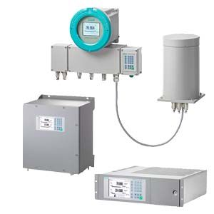
CALOMAT 7 module
- Заказные данные (1)
- Информационные материалы
Информационные материалы
The CALOMAT 7 module is primarily used for quantitative determination of H2 or He in digital or quasi-digital non-corrosive gas mixtures.
Concentrations of other gases can also be measured if their thermal conductivity differs significantly from their accompanying gases, such as Ar, CO2, CH4.
Область применения
Application areas
- Pure gas monitoring (0 to 0.5 % H2 in Ar)
- Protective gas monitoring (0 to 2 % He in N2)
- Hydroargon gas monitoring (0 to 25 % H2 in Ar)
- Forming gas monitoring (0 to 25 % H2 in N2)
- Gas production:
- 0 to 2 % He in N2
- 0 to 10 % Ar in O2
- Chemical applications:
- 0 to 2 % H2 in NH3
- 50 to 70 % H2 in N2
- Wood gasification (0 to 30 % H2 in CO/CO2/CH4)
- Blast furnace gas (0 to 5 % H2 in CO/CO2/CH4/N2)
- Bessemer converter gas (0 to 20 % H2 in CO/CO2)
Дизайн
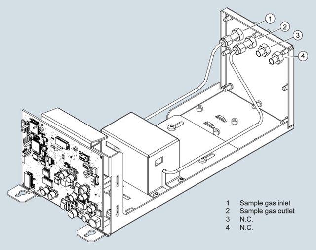
Structure of CALOMAT 7
Versions – parts wetted by sample gas
Gas path
Material
With pipes
Gas connection
Stainless steel, mat. no. 1.4571
Clamping rings and union nut (set)
Stainless steel, mat. no. 1.4401
Sample gas pipes
Stainless steel, mat. no. 1.4404
Sensor mounting block
Stainless steel, mat. no. 1.4571
Sensor
Si, SiOxNy, AU, epoxy resin, glass
Gasket, contained in the sensor module
Perfluorelastomere FFKM
Gas path
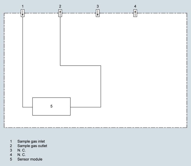
CALOMAT 7, gas path
Способ действия
The measuring method is based on the different levels of thermal conductivity of gases. CALOMAT 7 modules work with a micromechanically produced Si chip, the measuring membrane of which is equipped with thin-film resistors.
The resistors contained in the diaphragm are regulated for constant temperature. The amperage required fluctuates in accordance with the thermal conductivity of the sample gas. This raw value determined in this way is processed further electronically to calculate the gas concentration.
The sensor is in a thermostatically controlled stainless steel enclosure in order to suppress the effect of the ambient temperature. To rule out flow influences, the sensor is mounted in a bore hole next to the flow channel.
Note
The sample gases must be fed into the analyzers free of dust. Condensation (dew point sample gas < ambient temperature) is to be avoided in the sample chambers. Therefore, the use of gas modified for the measuring tasks is necessary in most application cases.
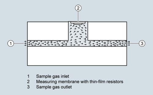
CALOMAT 7, mode of operation
Essential characteristics
- Four measuring ranges which can be freely configured, even with suppressed zero point, all measuring ranges are linear
- Smallest spans down to 0.5 % H2 (with suppressed zero: 95 to 100 % H2) possible
- Autoranging or manual measurement range switchover possible; remote switching is also possible
- Storage of measured values possible during adjustments
- Time constants can be selected within wide ranges (static/dynamic noise suppression); i.e. the response time of the device can be adapted to the respective measuring task.
- Short response time
- Low long-term drift
- Measuring point switchover for up to 6 measuring points (programmable)
- Measuring range identification
- Measuring point identification
- External pressure sensor can be connected – for correction of variations in sample gas pressure
- Automatic measuring range calibration can be configured
- Operation based on the NAMUR recommendation
Cross-interferences
To determine the cross-interferences of accompanying gases with several interfering gas components, you must know the sample gas composition. The following table contains the zero offsets for the carrier gas N2 as H2 equivalent values with 10% interference gas
Interference gas
H2 equivalent values with 10% interference gas
CH4
+1.77%
C2H6
+0.47%
C3H8
-0.28%
CO
-0.10%
CO2
-0.84%
O2
+0.19%
N2O
-0.83%
NH3
+1.45%
Ar
-1.22%
He
+6.32%
SF6
-2.15%
SO2
-1.47%
Synth. Air
+0.40%
H2O (3%)
+0.38%
Zero offset in the system H2 in N2
If you are using accompanying gas concentrations ≠ 10 %, you can use the corresponding multiples of the respective table value as an approximation. This procedure applies depending on the type of gas for an accompanying gas concentration range up to approx. 25%.
The thermal conductivity of most gas mixtures has a non-linear response. Even ambiguous results can occur in specific concentration ranges, e.g. with H2 in He mixtures.
In addition to the zero offset, the accompanying gas also affect the characteristic curve. For most gases, however, the effect on the characteristic curve is negligible.
Особенности
- Small T90 time due to micromechanical-produced Si sensor
- Universally applicable hardware basis, high measuring range dynamics (e.g. 0 to 0.5%, 0 to 100%, 95 to 100% H2)
- Open interface architecture (analog, digital, Ethernet)
- SIMATIC PDM network for maintenance and servicing information (optional)
Схема подключения
Gas connections
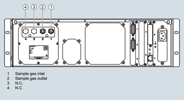
CALOMAT 7 gas connections
The sample gas connections are made of stainless steel with material no. 1.4571 and are designed as connecting fittings with a pipe diameter of 6 mm.
Технические данные
The technical specifications are based on the definitions of DIN EN 61207-1.
Unless specified otherwise, the data listed below relates to the following measurement conditions:
Ambient temperature
25 °C
Atmospheric pressure
Atmospheric (approx. 1 000 hPa)
Sample gas flow
0.6 l/min (or Nl/min)
Reference application
H2 in N2*
Site of installation
Vibration- and impact-free
* The technical specifications for time and measuring response as well as for the influencing variables can sometimes differ significantly for other gas mixtures
General information
Weight
Approx. 3 kg
Measuring ranges
Number of measuring ranges
Max. 4; parameters can be assigned freely
Parameters can be assigned in the measuring ranges
- Smallest possible span
0.5% H2 in N2
- Largest possible span
100% H2 in N2
- Smallest possible span with suppressed zero point
5% (e.g. 95% to 100%) H2 in N2
Gas inlet conditions
Sample gas pressure
700 to 1200 hPa (abs.)
Pressure drop between sample gas inlet and sample gas outlet
< 50 hPa at 1.5 l/min
Sample gas flow
30 to 90 l/h (0.5 to 1.5 l/min)
Sample gas temperature
0 to 70 °C
Sample gas humidity (rel. humidity)
< 90% (condensation inside the gas path is to be avoided)
Sample chamber temperature
Standard version
Approx. 72 °C
Time response
Warm-up period at room temperature
< 30 min (max. accuracy after 2 h)
Response characteristics
- Delay display T90 with device-internal signal damping (low pass filter) of 1 s
< 2.5 s
- Dead time (T10) at 1 l/min
< 0.5 s
- Adjustable signal damping range
0 to 100 s
Measuring response
Output signal fluctuation with device-internal signal damping of 1 s
≤ ± 0.5% of the smallest span acc. to nameplate (σ < ± 8.33 vpm H2)
Detection limit
≤ 1% of the smallest measuring span according to nameplate
Measured-value drift
≤ ± 1%/week of smallest span according to nameplate or ≤ 50 vpm H2 / week, whichever is greater
Repeatability
≤ ± 1% of the current measuring span or 100 vpm H2
Linearity error
≤ ± 1% of the current measuring span or 100 vpm H2
Influencing variables
Ambient temperature
≤ ± 0.5%1)/10 K of the current measuring span or ≤ ± 50 vpm H2 / 10 K
Sample gas pressure
≤ ± 0.5 %1) of the current measuring span/1% pressure variation or ≤ ± 50 vpm H2 / 1% pressure change
Sample gas flow
≤ ± 0.2% of the smallest possible measuring span with a change in flow of 1 dl/min within the permissible flow range
Accompanying gases (interference gases)
The interference gas sensitivity depends on the application and must be determined in each case except for applications with blast furnace gas / converter gas / wood gasification (pre-adjusted).
Supply voltage
≤ ± 0.1% of full-scale value (within the nominal range of use)
Electrical inputs and outputs
Analog and digital interfaces
See base unit
Climatic conditions
Storage and transport
-30 to 70 °C
Permissible ambient temperature (during operation in base unit)2)
0 to 50 °C
Relative humidity (RH) during storage, transport or operation
< 90% (condensation from the installed components is to be avoided)
Gas connections
Connection fittings
Pipe connection with 6 mm outer diameter
Materials of wetted parts
Gas connection
Stainless steel material no. 1.4571
Clamping rings and union nut (set)
Stainless steel material no. 1.4401
Sample gas pipes
Stainless steel material no. 1.4404
Sensor mounting block
Stainless steel material no. 1.4571
Sensor
Si, SiOxNy, Au, epoxy resin, glass
Gasket, contained in the sensor module
Perfluorelastomere FFKM
1) Values less than the detection limit are not useful
2) Restriction for installing an ULTRAMAT 7 module: 5 to 45 °C
Дальнейшая информация
Ordering example
CALOMAT 7 module built into wall box
7MB3000-3AX00-1AA0-Z+D12
7MB3040-0XX00-0BB0-Z+D12