
- Каталог оборудования Siemens
- Каталог продуктов Siemens Industry
- Приводная техника
- Техника автоматизации
- Системы автоматизации
- Системы визуализации SIMATIC HMI
- Системы идентификации
- Промышленные коммуникации SIMATIC NET
- Промышленные аппараты управления SIRIUS
- Промышленные информационные технологии
- Управление на базе РС
- Системы управления процессом
- Контрольно-измерительные приборы
- Анализаторы процесса
- Блоки питания SITOP
- Продукты для специальных требований
- Energy
- Автоматизация и безопасность зданий
- Низковольтная коммутационная техника
- Технология безопасности
- Системные решения и продукты для отраслей
- Сервис
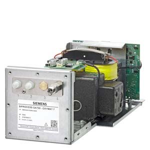
OXYMAT 7 module
- Заказные данные (1)
- Информационные материалы
Информационные материалы
The function of the OXYMAT 7 module is based on the paramagnetic alternating pressure method and is used to measure oxygen in gases.
Область применения
Application areas
- For boiler control in incineration plants
- In chemical plants
- For ultra-pure gas quality monitoring
- In environmental protection
- For quality control
- Purity control/air separator
Дизайн
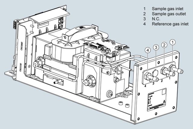
Structure of high-pressure version, standard module, sample gas path with pipes
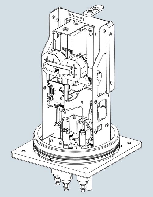
Structure of high-pressure version, field module, sample gas path with pipes
Designs – Parts wetted by sample gas, standard
Gas path
Material
With hoses
Bushing
PVDF
Hose
FKM (e.g. Viton)
Sample chamber
Stainless steel, mat. no. 1.4571
O-rings/seals
FPM
Restrictor
PTFE (e.g. Teflon)
With pipes
Bushing
Stainless steel, mat. no. 1.4571
Pipe
Stainless steel, mat. no. 1.4404
Sample chamber
Stainless steel, mat. no. 1.4571
Sample gas restrictor
Stainless steel, mat. no. 1.4571
O-rings/seals
FKM (Viton) or FFKM (Kalrez 6375)
Special applications
Materials adapted to the application
Gas path
High-pressure version with optional pressure switch for monitoring reference gas pressure
Reference gas pressure
2 000 … 4 000 hPa above sample gas pressure, but max. 5 000 hPa
Sample gas pressure
- With hoses
500 ... 1 500 hPa (abs.)
- With pipes
500 ... 2 500 hPa (abs.) with internal pressure sensor
500 ... 3 000 hPa (abs.) with external pressure sensor
Sample gas path
With hoses or with pipes
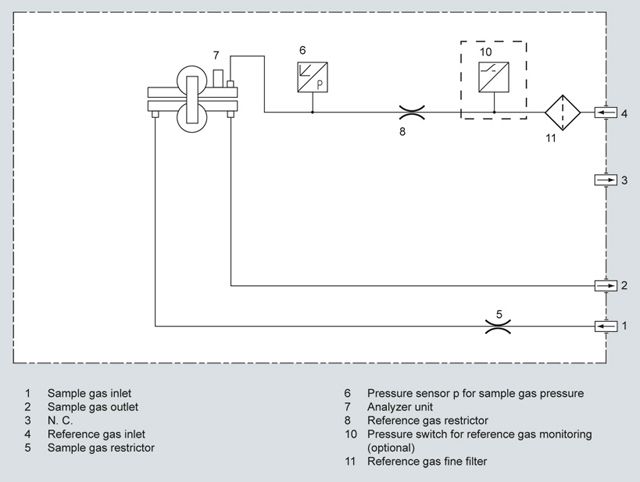
Gas path plan, high-pressure version with optional pressure switch for monitoring reference gas pressure
Low-pressure version with external reference gas pump
Reference gas pressure
100 hPa above the sample gas pressure (low-pressure version) for the connection of an external pump
Sample gas pressure
Atmospheric pressure ±50 hPa
Sample gas path
With hoses
Reference gas path
With hoses
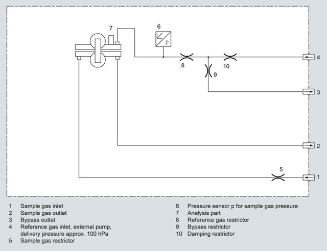
Gas path plan, low-pressure with external reference gas pump, with hoses
Способ действия
Oxygen is highly paramagnetic. This outstanding property of paramagnetism is used as a physical measuring effect for oxygen analysis.
Oxygen molecules in an inhomogeneous magnetic field always move toward the higher field strength. This results in a higher oxygen concentration where the field strength is higher (higher oxygen partial pressure). If two gases with differing oxygen content are combined in a magnetic field, a (O2 partial) pressure difference arises between them.
Since the measuring effect is always based on the difference of the oxygen content of the two gases, one refers to the sample and reference gases.
For measuring oxygen in the OXYMAT 7, the reference gas (N2, O2 or air) flows through two channels into the sample chamber (6). One of these partial flows enters the measuring chamber (7) in the area of the magnetic field. If the sample gas is O2-free, the reference gas can flow out freely. If the sample gas does contain O2, however, the oxygen molecules concentrate in the area of the magnetic field. The reference gas can then no longer flow off freely. An alternating pressure results between the two reference gas inlets. This pulsates in step with the magnetic field and depends on the oxygen concentration. This causes an alternating flow in the microflow sensor (4).
The microflow sensor consists of two nickel-plated grids heated to approximately 120ºC, which, along with two supplementary resistors, form a Wheatstone bridge. The alternating flow results in a change in the resistance of the nickel-plated grids. The resulting offset in the bridge is a measure of the concentration of oxygen in the sample gas.
Because the microflow sensor is located in the reference gas flow, the measurement is not influenced by the thermal conductivity, the specific heat or the internal friction of the sample gas. Additionally, the microflow sensor is protected through this arrangement from corrosion caused by the sample gas.
Further information
The oscillating magnetic field (8) means that the basic flow at the microflow sensor is not detected. The measurement is, thus, independent of the module's operating position or the position of the sample chamber.
The sample chamber is directly in the sample path and has a small volume, and the microflow sensor is a low-lag sensor. As a result, extremely short response times are realized.
Vibrations at the installation site can interfere with the measured signal (e.g. large fluctuations in the output signal). This behavior can be compensated for by a second (optional) microflow sensor (10), which functions as a vibration sensor. Since large differences in density between the sample and reference gases further amplify the undesired influence of vibration, reference gas is channeled to both the compensation microflow sensor (10) and the sample microflow sensor (4).
The sample gases must be fed into the analyzers free of dust. Condensation in the sample chambers must be prevented. Therefore, the use of gas modified for the measuring task is necessary in most application cases.
Flowing reference gas prevents the microflow sensor from being damaged and maintains the measurement capability of the module.
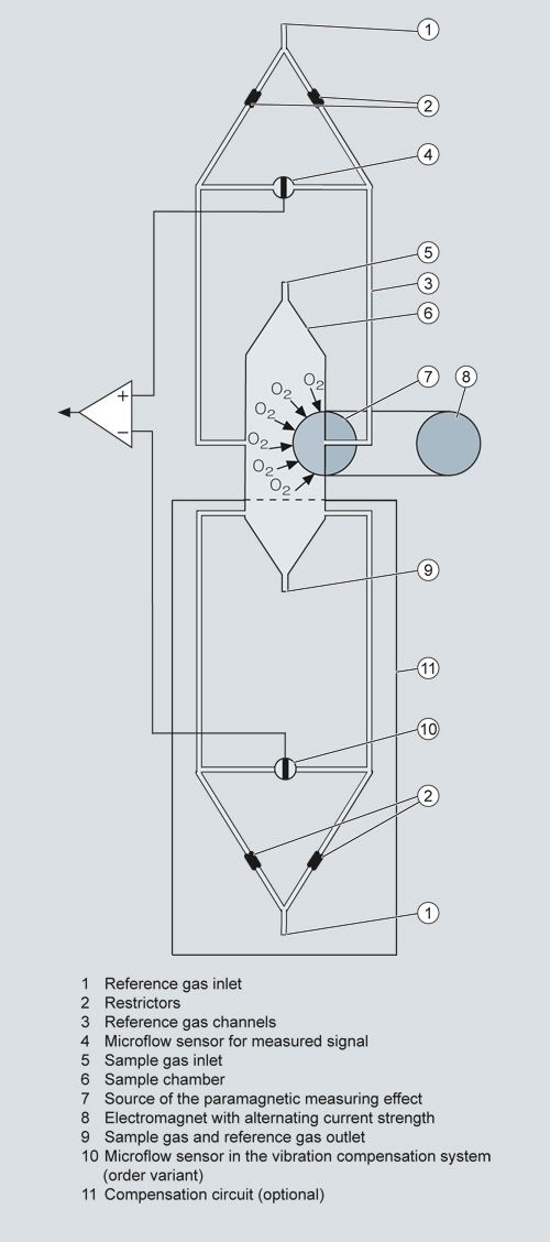
OXYMAT 7, principle of operation
Essential characteristics
Technical features
Depending on the reference gas, the physical zero point can be set between 0% and 100% oxygen.
- Smallest measuring spans (up to 0.5% O2) possible
- Measuring ranges with physically suppressed zero points possible (e.g. 99.5% to 100%)
- Short response time
- Low long-term drift
- Monitoring of reference gas pressure with reference gas connection 2 500 to 5 000 hPa (abs.) (option): reference gas pressure must be 2 000 ± 150 hPa higher than the sample gas pressure.
Features
- Internal pressure sensor for correction of pressure variations in sample gas in the range from 500 to 2 500 hPa (absolute)
- External pressure sensor - only with piping as the gas path - can be connected for correction of variations in the sample gas pressure up to 3 000 hPa absolute (option)
- Monitoring of reference gas (option)
- Analysis part with flow-type compensation circuit as an order variant for reducing the vibration impact at the installation site
- For sample gas path with hoses: Connection cable to the pressure sensor with hoses
- Hardware adapted to application
- Customer-specific analyzer options such as:
- Drift recording
- Kalrez gaskets
Reference gases
Measuring range
Recommended reference gas
Reference gas connection pressure
Comments
0 to ... vol.% O2
N2
2 000 … 4 000 hPa above sample gas pressure (max. 5 000 hPa absolute)
The reference gas flow is set automatically to 5 … 10 ml/min (up to 20 ml/min with flow-type compensation branch)
... to 100 vol.% O2 (suppressed zero point with full-scale value 100 vol.% O2)
O2
Around 21 vol.% O2 (suppressed zero point with 21 vol.% O2 within the measuring span)
Air
100 hPa with respect to sample gas pressure, which may vary by max. 50 hPa around the atmospheric pressure
Table 1: Reference gases for OXYMAT 7
Correction of zero-point error/cross-sensitivities
Accompanying gas (concentration 100 vol.%)
Zero point deviation in vol.% O2 absolute
Organic gases
Ethane C2H6
-0.49
Ethene (ethylene) C2H4
-0.22
Ethine (acetylene) C2H2
-0.29
1.2 butadiene C4H6
-0.65
1.3 butadiene C4H6
-0.49
n-butane C4H10
-1.26
iso-butane C4H10
-1.30
1-butene C4H8
-0.96
iso-butene C4H8
-1.06
Dichlorodifluoromethane (R12) CCl2F2
-1.32
Acetic acid CH3COOH
-0.64
n-heptane C7H16
-2.40
n-hexane C6H14
-2.02
Cyclo-hexane C6H12
-1.84
Methane CH4
-0.18
Methanol CH3OH
-0.31
n-octane C8H18
-2.78
n-pentane C5H12
-1.68
iso-pentane C5H12
-1.49
Propane C3H8
-0.87
Propylene C3H6
-0.64
Trichlorofluoromethane (R11) CCl3F
-1.63
Vinyl chloride C2H3Cl
-0.77
Vinyl fluoride C2H3F
-0.55
1.1 vinylidene chloride C2H2Cl2
-1.22
Inert gases
Helium He
+0.33
Neon Ne
+0.17
Argon Ar
-0.25
Krypton Kr
-0.55
Xenon Xe
-1.05
Inorganic gases
Ammonia NH3
-0.20
Hydrogen bromide HBr
-0.76
Chlorine Cl2
-0.94
Hydrogen chloride HCl
-0.35
Dinitrogen monoxide N2O
-0.23
Hydrogen fluoride HF
+0.10
Hydrogen iodide HI
-1.19
Carbon dioxide CO2
-0.30
Carbon monoxide CO
+0.07
Nitrogen oxide NO
+42.94
Nitrogen N2
0.00
Nitrogen dioxide NO2
+20.00
Sulfur dioxide SO2
-0.20
Sulfur hexafluoride SF6
-1.05
Hydrogen sulfide H2S
-0.44
Water H2O
-0.03
Hydrogen H2
+0.26
Table 2: Zero point error due to diamagnetism or paramagnetism of some accompanying gases with reference to nitrogen at 60 °C und 1 000 hPa absolute (according to IEC 1207/3)
Conversion to other temperatures:
The deviations from the zero point listed in Table 2 must be multiplied by a correction factor (k):
- with diamagnetic gases: k = 333 K / (ϑ [°C] + 273 K)
- with paramagnetic gases: k = [333 K / (ϑ [°C] + 273 K)]2
All diamagnetic gases have a negative deviation from zero point.
Особенности
Paramagnetic alternating pressure principle
- Small measuring ranges (0 to 0.5% or 99.5 to 100% O2)
- Absolute linearity
Detector element has no contact with the sample gas
- Applicable in the absence of corrosive sample gases
- Long service life
Physically suppressed zero point possible, e.g. in the measuring range 98% or 99.5% to 100% O2
Схема подключения
Gas connections
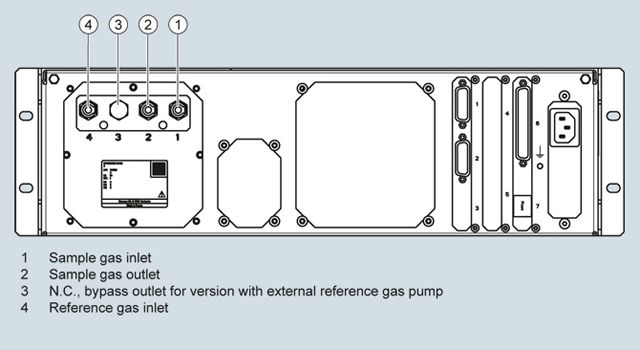
Gas connections for sample gas inlet and outlet, reference gas, purging gas (optional): Fittings, 6 mm pipe diameter
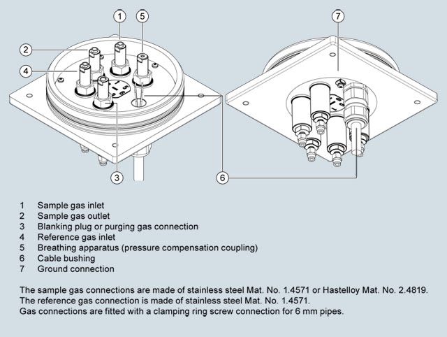
Gas connections of the field module
Технические данные
The technical specifications are based on the definitions of DIN EN 61207-1.
Unless specified otherwise, the data listed below relates to the following measurement conditions:
Ambient temperature
25 °C
Atmospheric pressure
Atmospheric (approx. 1 000 hPa)
Sample gas flow
0.6 l/min (or Nl/min)
Reference gas
Nitrogen
Site of installation
Vibration- and impact-free
General information
Weight
Approx. 5.5 kg (standard version)
Measuring ranges
Number of measuring ranges
Max. 4; parameters can be assigned freely
Parameters can be assigned in the measuring ranges
- Smallest possible measuring spans
0.5%, 1%, 2% or 5% O2
- Largest possible measuring span
100% O2
Gas inlet conditions
Sample gas pressure
- Standard devices with hoses
500 … 1 500 hPa (abs.)
- Standard devices with hoses and ext. RG pump
Atmospheric pressure ± 50 hPa
- Standard devices with pipes
500 … 3 000 hPa (abs.); briefly < 5 000 hPa (abs.)
- Field module
- For non-combustible gases
500 … 2 500 hPa (abs.)
- For combustible gases up to gas mixtures which are occasionally explosive
800 … 1 100 hPa (abs.)
Reference gas pressure
- High-pressure connection
2000 hPA above sample gas pressure (within permitted reference gas pressure range 2500 to 5000 hPa, abs.)
- Low-pressure connection with external reference gas pump
100 hPa above sample gas pressure
Pressure drop between sample gas inlet and sample gas outlet
< 100 hPa at 1 l/min
Sample gas flow
18 … 60 l/h (0.3 … 1 l/min)
Sample gas temperature
0 … 60 °C
Sample gas humidity (rel. humidity)
< 90% (condensation inside the gas path is to be avoided)
Sample chamber temperature
Standard version
Approx. 72 °C
Time response
Warm-up period at room temperature
< 2 h
Response characteristics
- Display delay T90 with an electronic damping setting of 0 s and a sample gas flow of 1 Nl/min.
≤ 1.9 s; ≤ 2.4 s (field module including flame arrestor)
- Dead time T10
≤ 1.1 s; < 1.6 s (field module)
Measuring response
Output signal fluctuation with static damping constant of 0 s and dynamic noise suppression of 5% / 10 s
≤ ±0.5% of smallest measuring span (noise bandwidth corresponds to 1% = 6σ value or 0.333% = 2σ value), with vibration compensation activated: < 1.5 times the value
Detection limit
≤ 1% of smallest measuring span according to nameplate (with vibration compensation activated: < 1.5 times the value)
Measured-value drift
- At the zero point
≤ ±0.5% of the smallest span/month or ≤ ±50 vpm O2/month, whichever is greater
- For span gas
≤ ±0.5% of the current measuring span/month or ≤ ±50 vpm O2/month, whichever is greater
Repeatability
- At the zero point
≤ ±0.5% of the smallest measuring span/month or ≤ ±50 vpm O2/month, whichever is greater
- For span gas
d≤ ±0.5% of the current measuring span/month or ≤ ±50 vpm O2, whichever is greater
Linearity error with dry ambient air1)
< 0.1%
Influencing variables
Ambient temperature
- Deviation at zero point
≤ 0.5% of the smallest measuring span / 10 K or ≤ 50 vpm O2/10 K, whichever is greater
- Deviation of the span gas
≤ 0.5% of the current measuring span / 10 K or ≤ 50 vpm O2/10 K, whichever is greater
Sample gas pressure
- Deviation at zero point
≤ 0.2% of the smallest measuring span / 1% pressure variation or ≤ 50 vpm O2/1% pressure variation, whichever is greater
- Deviation of the span gas
≤ 0.2% of the current measuring span / 1% pressure variation or ≤ 50 vpm O2/1% pressure variation, whichever is greater
Sample gas flow
- Deviation at zero point
≤ 1% of smallest measuring span per 0.1 l/min change in flow or ≤ 50 vpm O2 per 0.1 l/min change in flow within the permissible flow range (0.3 to 1 l/min), whichever is greater
- Deviation of the span gas
≤ 1% of current measuring span per 0.1 l/min change in flow or ≤ 50 vpm O2 per 0.1 l/min change in flow within the permissible flow range (0.3 to 1 l/min), whichever is greater
Accompanying gases
Zero point deviation (cross-sensitivity) in accordance with Table A.1 of EN 61207-3
Supply voltage
< 0.1% of the current measuring span (within the nominal range of use)
Electrical inputs and outputs
Analog and digital interfaces
See base unit
Gas connections
Connection fittings
Pipe connection with 6 mm outer diameter
Climatic conditions
Storage and transport
-30 to 70 °C
Permissible ambient temperature (during operation in base unit)2)
0 to 50 °C
Relative humidity (RH) during storage, transport or operation
< 90% (condensation from the installed components is to be avoided)
Materials of wetted parts
Sample chamber
Stainless steel:
- Plates: Mat. No. 1.4571 (X6CrNiMoTi 17-12-2)
- Screw-in glands: Mat. No. 1.4404 (X2CrNiMo17-12-2)
Internal gas path
- With hoses
FPM (e.g. Viton), gas connections of stainless steel material no. 14404 (X2CrNiMo 17-12-2)
- With pipes
Stainless steel:
- Pipes: Mat. No. 1.4571 (X6CrNiMoTi 17-12-2)
- Gas connections: Mat. No. 1.4404 (X2CrNiMo 17-12-2)
Sealing material
FPM (e.g. Viton) or FFKM (e.g. Kalrez 6375)
Special applications
Gas path
- With pipes
Materials adapted to the application
1) Untreated ambient air contains less than 20.95% O2 (literature value) since existing humidity of the oxygen content is decreased relatively.
2) Restriction for installing an ULTRAMAT 7 module: 5 to 45 °C
Дальнейшая информация
Ordering example
OXYMAT 7 module built into wall box
7MB3000-3AX00-1AA0-Z+D02
7MB3020-0CE00-0AA0-Z+D02OXYMAT 7 module and ULTRAMAT 7 module built into rack-mounted enclosure
7MB3000-0AA00-1AA0-Z+D05
7MB3020-0CE00-0AA0-Z+D05
7MB3010-0CA10-0AA0-Z+D05OXYMAT 7 module and wall box supplied unassembled
7MB3000-3AX00-1AA0
7MB3020-0CE00-0AA0