
- Каталог оборудования Siemens
- Каталог продуктов Siemens Industry
- Приводная техника
- Преобразователи
- Стандартные преобразователи
- Общая информация о базовых преобразователях SINAMICS V
- Преобразователи частоты общего назначения SINAMICS G
- Высокопроизводительные преобразователи SINAMICS S
- MICROMASTER
- SIPLUS POSMO A
- SIMODRIVE POSMO
- LOHER DYNAVERT Drive System
- Преобразователи на среднее напряжение
- Преобразователи постоянного тока
- Стандартные преобразователи
- Двигатели переменного тока
- Generators
- Мотор-редукторы
- Flender Gear Units
- Couplings
- Инструментальное программное обеспечение
- Дополнительные компоненты
- Преобразователи
- Техника автоматизации
- Energy
- Автоматизация и безопасность зданий
- Низковольтная коммутационная техника
- Технология безопасности
- Системные решения и продукты для отраслей
- Сервис
- Приводная техника
Active Interface Modules
- Информационные материалы
Информационные материалы
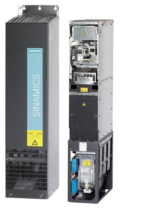
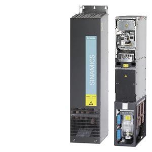
Active Interface Modules are used in conjunction with Active Line Modules. Active Interface Modules contain a Clean Power Filter with basic RI suppression, the pre-charging circuit for the Active Line Module, the line voltage sensing circuit and monitoring sensors. The bypass contactor is an integral component in types FI and GI. This ensures a highly compact design. The bypass contactor must be provided separately for frame sizes HI and JI.
Line harmonics are largely suppressed by the Clean Power Filter.
Дизайн
Active Interface Modules have the following interfaces as standard:
- 1 line supply connection
- 1 load connection
- 1 connection for the 24 V DC electronics power supply
- 1 connection for the external 230 V AC supply (fan power supply)
- 1 DRIVE‑CLiQ socket (on VSM10 Voltage Sensing Module)
- 1 connection for pre-charging circuit, frame sizes HI and JI
- 1 PE connection
The scope of supply of the Active Interface Modules includes:
- DRIVE-CLiQ cable for the connection between Active Interface Module and Active Line Module
- 1 set of warning labels in 30 languages
(BG, CN, CZ, DE, DK, EE, ES, FI, FR, GB, GR, HU, IE, IS, IT, JP, KR, LT, LV, MT, NL, NO, PL, PT, RO, RU, SE, SI, SK, TR)
Интеграция
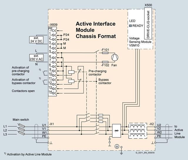
Connection example of an Active Interface Module with integrated bypass contactor (frame sizes FI and GI)
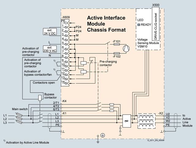
Connection example of an Active Interface Module with externally mounted bypass contactor (frame sizes HI and JI)
Технические данные
Line voltage 380 ... 480 V 3 AC
Active Interface Modules
6SL3300-7TE32-6AA0
6SL3300-7TE33-8AA0
6SL3300-7TE35-0AA0
Suitable for Active Line Module
- Rated power at 400 V
kW
132
160
235
300
- Air-cooled
6SL3330-7TE32-1AA3
6SL3330-7TE32-6AA3
6SL3330-7TE33-8AA3
6SL3330-7TE35-0AA3
- Liquid-cooled
–
–
–
6SL3335-7TE35-0AA3
Rated current
A
210
260
380
490
Bypass contactor
Included
Included
Included
Included
Current demand
- 24 V DC auxiliary power supply
A
0.17
0.17
0.17
0.17
- 230 V 2 AC
- Inrush current
A
1.25
1.25
2.5
2.5
- Holding current
A
0.6
0.6
1.2
1.2
DC link capacitance
of drive line-up, max. 1)
μF
41600
41600
76800
76800
Power loss, max. 2)
- At 50 Hz 400 V
kW
2.1
2.2
3.0
3.9
- At 60 Hz 460 V
kW
2.1
2.2
3.0
3.9
Cooling air requirement
m3/s (ft3/s)
0.24 (8.5)
0.24 (8.5)
0.47 (16.6)
0.47 (16.6)
Line/load connection
L1, L2, L3 / U2, V2, W2
Flat connector for M10 screw
Flat connector for M10 screw
Flat connector for M10 screw
Flat connector for M10 screw
- Conductor cross section, max. (IEC)
mm2
2 × 185
2 × 185
2 × 185
2 × 185
PE/GND connection
2 × M10 nut
2 × M10 nut
2 × M10 nut
2 × M10 nut
- Conductor cross section, max. (IEC)
mm2
2 × 185
2 × 185
2 × 185
2 × 185
Degree of protection
IP20
IP20
IP20
IP20
Dimensions
- Width
mm (in)
325 (12.8)
325 (12.8)
325 (12.8)
325 (12.8)
- Height
mm (in)
1400 (55.1)
1400 (55.1)
1533 (60.3)
1533 (60.3)
- Depth
mm (in)
355 (14.0)
355 (14.0)
544 (21.4)
544 (21.4)
Weight, approx.
kg (lb)
135 (298)
135 (298)
190 (419)
190 (419)
Frame size
FI
FI
GI
GI
Minimum short-circuit current 3)
A
6200
10500
10500
8000
1)Information on higher capacities is included in the SINAMICS Low Voltage Engineering Manual.
2) The specified power loss represents the maximum value at 100% utilization. The value is lower under normal operating conditions.
3) Current required for reliable triggering of the protective devices.
Line voltage 380 ... 480 V 3 AC
Active Interface Modules
6SL3300-7TE38-4AA0
6SL3300-7TE41-4AA0
Suitable for Active Line Module
- Rated power at 400 V
kW
380
450/500
630
800/900
- Air-cooled
6SL3330-7TE36-1AA3
6SL3330-7TE37-5AA3
6SL3330-7TE38-4AA36SL3330-7TE41-0AA3
6SL3330-7TE41-2AA3
6SL3330-7TE41-4AA3- Liquid-cooled
6SL3335-7TE36-1AA3
6SL3335-7TE38-4AA3
–
–
Rated current
A
605
745/840
985
1260/1405
Bypass contactor
3RT1476-6AP36
3WL1110-2BB34-4AN2-Z
Z = C22 1)3WL1112-2BB34-4AN2-Z
Z = C22 1)3WL1116-2BB34-4AN2-Z
Z = C22 1)Current demand
- 24 V DC auxiliary power supply
A
0.17
0.17
0.17
0.17
- 230 V 2 AC
- Inrush current
A
9.9
9.9
10.5
10.5
- Holding current
A
4.6
4.6
4.9
4.9
DC link capacitance
of the drive line-up, max. 2)
μF
134400
134400
230400
230400
Power loss, max. 3)
- At 50 Hz 400 V
kW
5.5
6.1
7.5
8.5
- At 60 Hz 460 V
kW
5.5
6.1
7.5
8.5
Cooling air requirement
m3/s (ft3/s)
0.4 (14.1)
0.4 (14.1)
0.4 (14.1)
0.4 (14.1)
Line/load connection
L1, L2, L3 / U2, V2, W2
4 × hole for M12
4 × hole for M12
3 × hole for M12
3 × hole for M12
- Conductor cross section, max. (IEC)
mm2
4 × 240
4 × 240
6 × 240
6 × 240
PE/GND connection
2 × M12 nut
2 × M12 nut
4 × M12 nut
4 × M12 nut
- Conductor cross section, max. (IEC)
mm2
2 × 240
2 × 240
4 × 240
4 × 240
Degree of protection
IP00
IP00
IP00
IP00
Dimensions
- Width
mm (in)
305 (12.0)
305 (12.0)
505 (19.9)
505 (19.9)
- Height
mm (in)
1750 (68.9)
1750 (68.9)
1750 (68.9)
1750 (68.9)
- Depth
mm (in)
544 (21.4)
544 (21.4)
544 (21.4)
544 (21.4)
Weight, approx.
kg (lb)
390 (960)
390 (960)
480 (1058)
480 (1058)
Frame size
HI
HI
JI
JI
Minimum short-circuit current 4)
A
9200
8800/10400
16000
21000
1) The breakers must always be switched ON and OFF by the sequence control. An interlocking set 3WL9111‑0BA21‑0AA0 as described in Catalog LV 10 should be provided for the bypass contactor to exclude the risk of unintentional manual operation. Manual operation bypasses the pre-charging circuit and can therefore destroy the Active Line Module.
2)Information on higher capacities is included in the SINAMICS Low Voltage Engineering Manual.
3) The specified power loss represents the maximum value at 100% utilization. The value is lower under normal operating conditions.
4) Current required for reliably triggering protective devices.
Line voltage 500 ... 690 V 3 AC
Active Interface Modules
6SL3300-7TG35-8AA0
6SL3300-7TG37-4AA0
6SL3300-7TG41-3AA0
Suitable for Active Line Module
- Rated power at 690 V
kW
630
800
1100
1400
- Air-cooled
6SL3330-7TG35-8AA3
6SL3330-7TG37-4AA3
6SL3330-7TG41-0AA3
6SL3330-7TG41-3AA3
- Liquid-cooled
6SL3335-7TG35-8AA3
–
–
–
Rated current
A
575
735
1025
1270
Bypass contactor
3RT1476-6AP36
3RT1476-6AP36 (3 units)
3WL1212-4BB34-4AN2-Z
C22 1)3WL1216-4BB34-4AN2-Z
C22 1)Current demand
- 24 V DC auxiliary power supply
A
0.17
0.17
0.17
0.17
- 230 V 2 AC
- Inrush current
A
9.9
10.5
10.5
10.5
- Holding current
A
4.6
4.9
4.9
4.9
DC link capacitance
of the drive line-up, max. 2)
μF
59200
153600
153600
153600
Power loss, max. 3)
- At 50 Hz 690 V
kW
6.8
9.0
9.2
9.6
- At 60 Hz 575 V
kW
6.8
9.0
9.2
9.6
Cooling air requirement
m3/s (ft3/s)
0.4 (14.1)
0.4 (14.1)
0.4 (14.1)
0.4 (14.1)
Line/load connection
L1, L2, L3 / U2, V2, W2
4 × hole for M12
3 × hole for M12
3 × hole for M12
3 × hole for M12
- Conductor cross section, max. (IEC)
mm2
4 × 240
6 × 240
6 × 240
6 × 240
PE/GND connection
2 × M12 nut
4 × M12 nut
4 × M12 nut
4 × M12 nut
- Conductor cross section, max. (IEC)
mm2
2 × 240
4 × 240
4 × 240
4 × 240
Degree of protection
IP00
IP00
IP00
IP00
Dimensions
- Width
mm (in)
305 (12.0)
505 (19.9)
505 (19.9)
505 (19.9)
- Height
mm (in)
1750 (68.9)
1750 (68.9)
1750 (68.9)
1750 (68.9)
- Depth
mm (in)
544 (21.4)
544 (21.4)
544 (21.4)
544 (21.4)
Weight, approx.
kg (lb)
390 (960)
430 (948)
530 (1169)
530 (1169)
Frame size
HI
JI
JI
JI
Minimum short-circuit current 4)
A
8400
10500
16000
20000
1) The breakers must always be switched ON and OFF by the sequence control. An interlocking set 3WL9111‑0BA21‑0AA0 as described in Catalog LV 10 should be provided for the bypass contactor to exclude the risk of unintentional manual operation. Manual operation bypasses the pre-charging circuit and can therefore destroy the Active Line Module.
2) Information on higher capacities is included in the SINAMICS Low Voltage Engineering Manual.
3) The specified power loss represents the maximum value at 100% utilization. The value is lower under normal operating conditions.
4) Current required for reliably triggering protective devices.