
- Каталог оборудования Siemens
- Каталог продуктов Siemens Industry
- Приводная техника
- Преобразователи
- Стандартные преобразователи
- Общая информация о базовых преобразователях SINAMICS V
- Преобразователи частоты общего назначения SINAMICS G
- Преобразователи частоты SINAMICS G110
- Компактные преобразователи SINAMICS G120C
- Преобразователи для насосов, вентиляторов,компрессоров SINAMICS G120P
- Стандартные преобразователи SINAMICS G120
- SINAMICS G110M distributed inverters
- Преобразователь частоты SINAMICS G110D для распределенной периферии
- Преобразователи частоты SINAMICS G120D
- Преобразователи SINAMICS G130 формат шасси
- Преобразователь частоты SINAMICS G150 шкафного исполнения
- SINAMICS G180
- Высокопроизводительные преобразователи SINAMICS S
- MICROMASTER
- SIPLUS POSMO A
- SIMODRIVE POSMO
- LOHER DYNAVERT Drive System
- Преобразователи на среднее напряжение
- Преобразователи постоянного тока
- Стандартные преобразователи
- Двигатели переменного тока
- Generators
- Мотор-редукторы
- Flender Gear Units
- Couplings
- Инструментальное программное обеспечение
- Дополнительные компоненты
- Преобразователи
- Техника автоматизации
- Energy
- Автоматизация и безопасность зданий
- Низковольтная коммутационная техника
- Технология безопасности
- Системные решения и продукты для отраслей
- Сервис
- Приводная техника
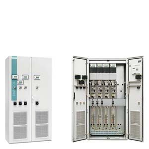
SINAMICS G180 cabinet systems
- Заказные данные (63)
- Информационные материалы
Информационные материалы
SINAMICS G180 cabinet systems comprise SINAMICS G180 compact units which are combined with Rittal TS8 cabinets and customer-specific control accessories to create individual cabinet systems.
Global use
SINAMICS G180 converter cabinet systems are manufactured in compliance with relevant international standards and regulations, and are therefore suitable for global use (see technical data).
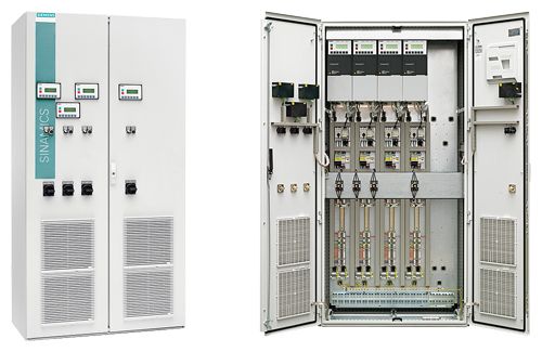
SINAMICS G180 – cabinet system with four compact units
Дизайн
- Modular principle permits the design of cost-optimized, customized systems
- A complete installation can be quickly and easily assembled through the integration of various industry-specific control packages
- Use of CAE/CAM systems increases flexibility and shortens delivery times
- Capable of integration in any control concept thanks to customized design
- Capable of adaptation to numerous bus systems
- Overall concept is devised to minimize space requirements
- Rittal TS8 cabinet system ensures acceptance anywhere in the world
- Optimum use of space thanks to different cabinet sizes
- Easy to adapt to an extensive range of climatic conditions
- Quick access to all components from front of cabinet eases maintenance
- Additional fans are not generally required
- Cable entry from below incl. cable clamping bar, shielding bus and grounding bar
Number of compact units in cabinet system (depending on width)
Compact units
Cabinet system width
600 mm
800 mm
1000 mm
1200 mm
165 mm wide
2.2 … 11 kW (400 V)
2.2 … 15 kW (500 V)
3
4
5
6
225 mm wide
15 … 30 kW (400 V)
22 … 37 kW (500 V)
7.5 … 22 kW (690 V)
2
3
4
4
350 mm wide
37 … 110 kW (400 V)
45 … 132 kW (500 V)
30 … 132 kW (690 V)
1
2
2
3
500 mm wide
132 … 160 kW (400 V)
160 … 200 kW (500 V)
160 … 200 kW (690 V)
1
1
1
2
This overview applies to cabinet systems without an additional control system (except for option S31). We would be happy to assist with optimization of the cabinet system width.
Чертеж
Standard cabinet size for cabinet systems (option H81)
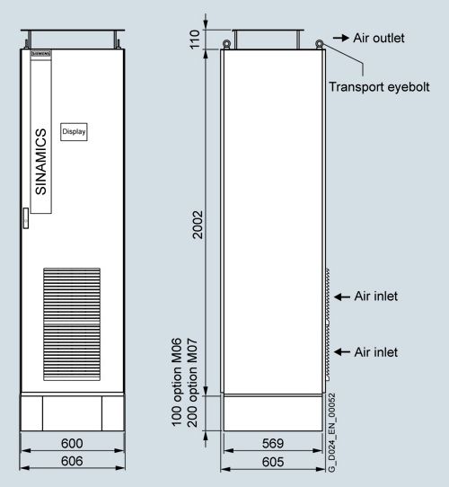
Dimensional drawing applies to standard cabinet systems (option H81) with converter without options. The cabinet dimensions might change if options are selected.
Опции
The following tables provide an overview of the options and their availability for SINAMICS G180 compact units in control cabinets (cabinet systems) with a supply voltage of 400 V, 500 V or 690 V. (For details, see catalog chapter 4 "Option descriptions".)
SINAMICS G180 cabinet systems (compact units installed in a control cabinet)
400 V TN/TT system
500 V IT system
Version – see selection and ordering data
Option text
Additional ordering data -Z with order code and, if necessary, with plain text specification
A
B
C
D
E
F
G
H
I
J
K
L
Converter cabinet width
406 mm
H80
✓
✓
✓
–
–
–
✓
✓
✓
–
–
–
606 mm
H81
❑
❑
❑
❑
❑
❑
❑
❑
❑
❑
❑
❑
806 mm
H82
✓
✓
✓
✓
✓
✓
✓
✓
✓
✓
✓
✓
1006 mm
H83
✓
✓
✓
✓
✓
✓
✓
✓
✓
✓
✓
✓
1206 mm
H84
✓
✓
✓
✓
✓
✓
✓
✓
✓
✓
✓
✓
1406 mm
H85
✓
✓
✓
✓
✓
✓
✓
✓
✓
✓
✓
✓
1606 mm
H86
✓
✓
✓
✓
✓
✓
✓
✓
✓
✓
✓
✓
Additional cabinet
400 mm
H90
✓
✓
✓
✓
✓
✓
✓
✓
✓
✓
✓
✓
600 mm
H91
✓
✓
✓
✓
✓
✓
✓
✓
✓
✓
✓
✓
800 mm
H92
✓
✓
✓
✓
✓
✓
✓
✓
✓
✓
✓
✓
1000 mm
H93
✓
✓
✓
✓
✓
✓
✓
✓
✓
✓
✓
✓
1200 mm
H94
✓
✓
✓
✓
✓
✓
✓
✓
✓
✓
✓
✓
Line voltages
Line voltage 380 V, 50 Hz
V70
✓
✓
✓
✓
✓
✓
✓
✓
✓
✓
✓
✓
Line voltage 400 V, 50 Hz
V71
✓
✓
✓
✓
✓
✓
✓
✓
✓
✓
✓
✓
Line voltage 415 V, 50 Hz
V72
✓
✓
✓
✓
✓
✓
✓
✓
✓
✓
✓
✓
Line voltage 500 V, 50 Hz
V73
✓
✓
✓
✓
✓
✓
✓
✓
✓
✓
✓
✓
Line voltage 660 V, 50 Hz
V74
–
–
–
–
–
–
–
–
–
–
–
–
Line voltage 690 V, 50 Hz
V75
–
–
–
–
–
–
–
–
–
–
–
–
Line voltage 440 V, 60 Hz
V76
✓
✓
✓
✓
✓
✓
✓
✓
✓
✓
✓
✓
Line voltage 460 V, 60 Hz
V77
✓
✓
✓
✓
✓
✓
✓
✓
✓
✓
✓
✓
Line voltage 480 V, 60 Hz
V78
✓
✓
✓
✓
✓
✓
✓
✓
✓
✓
✓
✓
Line voltage 600 V, 60 Hz
V79
–
–
–
–
–
–
–
–
–
–
–
–
Line voltage 660 V, 60 Hz
V80
–
–
–
–
–
–
–
–
–
–
–
–
Special line voltage; please specify voltage
Y70 • and identification code
✓1)
✓1)
✓1)
✓1)
✓1)
✓1)
✓1)
✓1)
✓1)
✓1)
✓1)
✓1)
External auxiliary power supply
Connection for 230 V 1 AC 50 Hz auxiliary voltage provided by customer
C36
✓
✓
✓
✓
✓
✓
✓
✓
✓
✓
✓
✓
Connection for 400 V 3 AC 50 Hz auxiliary voltage provided by customer
C38
✓
✓
✓
✓
✓
✓
✓
✓
✓
✓
✓
✓
Connection for 500 V 3 AC 50 Hz auxiliary voltage provided by customer
C43
✓
✓
✓
✓
✓
✓
✓
✓
✓
✓
✓
✓
Connection for 690 V 3 AC 50 Hz auxiliary voltage provided by customer
C48
✓
✓
✓
✓
✓
✓
✓
✓
✓
✓
✓
✓
Connection for other 3 AC voltage provided by customer; please specify voltage
Y36 • and identification code
✓
✓
✓
✓
✓
✓
✓
✓
✓
✓
✓
✓
External control voltage supply
Connection for 230 V 1 AC 50 Hz control voltage provided by customer, without UPS backup
C56
✓
✓
✓
✓
✓
✓
✓
✓
✓
✓
✓
✓
Connection for 230 V 1 AC 50 Hz control voltage provided by customer, with UPS backup
C57
✓
✓
✓
✓
✓
✓
✓
✓
✓
✓
✓
✓
Connection for different 1 AC control voltage (47 to 63 Hz) provided by customer; please specify voltage
Y55 • and identification code
✓
✓
✓
✓
✓
✓
✓
✓
✓
✓
✓
✓
RFI suppression filter
RFI suppression filter, category C2 or C3 (class A)
L00
❑
❑
❑
❑
❑
❑
–
–
–
–
–
–
RFI suppression filter, category C1 (class B)
L02
✓
✓
✓
✓
✓
✓
–
–
–
–
–
–
Line Harmonics Filter
Line Harmonics Filter for 50 Hz line frequency up to 500 V
L03
H813)
H813)
H823)
H823)
H813)
+
H913)H813)
+
H913)H813)
H813)
H823)
H823)
H813)
+
H913)H813)
+
H913)Line Harmonics Filter for 60 Hz line frequency up to 480 V
L04
H813)
H813)
H823)
H823)
H813)
+
H913)H813)
+
H913)H813)
H813)
H823)
H823)
H813)
+
H913)H813)
+
H913)Output filter
Strengthened dv/dt output filter for max. 250/300 m (type-dependent). Design for longer motor cables available on request
L10
✓
✓
✓
✓
✓
✓
❑
❑
❑
❑
❑
❑
Sine-wave filter integrated in control cabinet, suitable for motor frequencies of ≤ 75 Hz, voltage drop of approximately 5 % of line voltage
L17
✓
✓
✓
✓
✓
H813)
+
H913)✓
✓
✓
✓
✓
H813)
+
H913)Standard accessories packages
Peripheral board 4 (G05) instead of peripheral board 2 (G03) (only in conjunction with package S01, S02, S03, S04, S08, S09, S11, S12)
G08
✓
✓
✓
✓
✓
✓
✓
✓
✓
✓
✓
✓
Accessories package S01 with main switch, line contactor, EMERGENCY OFF pushbutton and safety relay, board G03, local/remote switch
S01
✓
✓
✓
✓
✓
✓
✓
✓
✓
✓
✓
✓
Accessories package S02 with circuit breaker, line contactor, EMERGENCY OFF pushbutton and safety relay, board G03, local/remote switch
S02
✓
✓
✓
✓
✓
✓
✓
✓
✓
✓
✓
✓
Accessories package with main switch, line contactor, board G03, local/remote switch
S03
✓
✓
✓
✓
✓
✓
✓
✓
✓
✓
✓
✓
Accessories package with circuit breaker, line contactor, board G03, local/remote switch
S04
✓
✓
✓
✓
✓
✓
✓
✓
✓
✓
✓
✓
Accessories package with main switch, line contactor, Calomat, RCU box connection
S06
✓
✓
✓
✓
✓
✓
✓
✓
✓
✓
✓
✓
Bypass for smooth line synchronization (soft start function) incl. line-side main switch and contactors at the converter output and in bypass
S08
✓
✓
✓
✓
H823)
H833)
✓
✓
✓
✓
H823)
H833)
Bypass for smooth line synchronization (soft start function) incl. line-side circuit breaker and contactors at the converter output and in bypass
S09
✓
✓
✓
✓
H823)
H833)
✓
✓
✓
✓
H823)
H833)
Accessories package S11 with line-side main switch, board G03, local/remote switch
S11
✓
✓
✓
✓
✓
✓
✓
✓
✓
✓
✓
✓
Accessories package S12 with line-side circuit breaker, board G03, local/remote switch
S12
✓
✓
✓
✓
✓
✓
✓
✓
✓
✓
✓
✓
Bypass with line-side main switch, contactors at converter output and in bypass, switchover between manual and automatic, local/remote switch
S21
✓
✓
✓
✓
H823)
H833)
✓
✓
✓
✓
H823)
H833)
Bypass with line-side circuit breaker, contactors at converter output and in bypass, switchover between manual and automatic, local/remote switch
S22
✓
✓
✓
✓
H823)
H833)
✓
✓
✓
✓
H823)
H833)
Bypass with line-side main switch, contactors at converter output and in bypass, EMERGENCY OFF safety relay, switchover between manual and automatic, local/remote switch
S23
✓
✓
✓
✓
H823)
H833)
✓
✓
✓
✓
H823)
H833)
Bypass with line-side circuit breaker, contactors at converter output and in bypass, EMERGENCY OFF safety relay, switchover between manual and automatic, local/remote switch
S24
✓
✓
✓
✓
H823)
H833)
✓
✓
✓
✓
H823)
H833)
NAMUR accessories package with Test/Normal operation switch, option G05, terminal strip compliant with NAMUR NE37 (without main switch)
S31
✓
✓
✓
✓
✓
✓
✓
✓
✓
✓
✓
✓
NAMUR accessories package with Test/Normal operation switch, main switch, line contactor, option G05, terminal strip compliant with NAMUR NE37
S32
✓
✓
✓
✓
✓
✓
✓
✓
✓
✓
✓
✓
Braking chopper
Braking chopper integrated into converter (braking resistor is not included and must be ordered separately)
L72
❑
✓
✓
✓
✓
✓
❑
✓
✓
✓
✓
✓
CALOMAT CK145
CALOMAT CK145 without storage for motor temperature prewarning
L80
✓
✓
✓
✓
✓
✓
✓
✓
✓
✓
✓
✓
CALOMAT CK145 with storage for motor temperature trip
L81
✓
✓
✓
✓
✓
✓
✓
✓
✓
✓
✓
✓
CALOMAT CK145 without storage for transformer temperature prewarning
L82
✓
✓
✓
✓
✓
✓
✓
✓
✓
✓
✓
✓
CALOMAT CK145 with storage for transformer temperature trip
L83
✓
✓
✓
✓
✓
✓
✓
✓
✓
✓
✓
✓
CALOMAT CK145 for other PTC thermistor monitoring functions
Y80 • and identification code
✓
✓
✓
✓
✓
✓
✓
✓
✓
✓
✓
✓
Pt100 evaluation unit
Pt100 evaluation unit for motor winding temperature, integrated in control cabinet for monitoring of 3 × Pt100 or 3 × KTY83/84 sensors
L90
✓
✓
✓
✓
✓
✓
✓
✓
✓
✓
✓
✓
Pt100 evaluation unit for motor bearing temperature, integrated in control cabinet for monitoring of 2 × Pt100 or 2 × KTY83/84 sensors
L91
✓
✓
✓
✓
✓
✓
✓
✓
✓
✓
✓
✓
Pt100 evaluation unit for motor winding temperature, integrated in cabinet for monitoring 3 × Pt100 sensors; plus an analog output (0 to 10 V or 0(4) to 20 mA) connected to terminals for the hottest winding temperature
L92
✓
✓
✓
✓
✓
✓
✓
✓
✓
✓
✓
✓
Pt100 evaluation unit for motor bearing temperature, integrated in cabinet for monitoring 2 × Pt100 sensors or 2 × KTY83/84 sensors; plus two analog outputs (0 to 10 V or 0(4) to 20 mA) connected to terminals for bearing temperature
L93
✓
✓
✓
✓
✓
✓
✓
✓
✓
✓
✓
✓
Pt100 evaluation unit for motor winding and bearing temperatures, integrated in cabinet for monitoring 6 × Pt100 sensors; plus two analog outputs (0 to 10 V or 0(4) to 20 mA) connected to terminals for the hottest winding and bearing temperatures
L94
✓
✓
✓
✓
✓
✓
✓
✓
✓
✓
✓
✓
Pt100 evaluation unit for other temperature monitoring functions, integrated in cabinet for monitoring of 3 × Pt100 or 3 × KTY83/84 sensors
Y90 • and identification code
✓
✓
✓
✓
✓
✓
✓
✓
✓
✓
✓
✓
Pt100 evaluation unit for other temperature monitoring functions, integrated in cabinet for monitoring 6 × Pt100 sensors; plus two analog outputs (0 to 10 V or 0(4) to 20 mA) connected to terminals
Y94 • and identification code
✓
✓
✓
✓
✓
✓
✓
✓
✓
✓
✓
✓
Degrees of protection
Increased degree of protection IP41 for air-cooled cabinet units and systems
M41
✓
✓
✓
✓
✓
✓
✓
✓
✓
✓
✓
✓
Increased degree of protection IP43 for air-cooled cabinet units and systems
M43
✓
✓
✓
✓
✓
✓
✓
✓
✓
✓
✓
✓
Increased degree of protection IP54 for air-cooled cabinet units and systems; not suitable for outdoor applications
M54
✓
✓
✓
✓
✓
✓
✓
✓
✓
✓
✓
✓
Air flange for connection to customer's exhaust air systems (air outlet IP00)
M63
✓
✓
✓
✓
✓
✓
✓
✓
✓
✓
✓
✓
Cabinet options
Control cabinet base, welded and suitable for use with transport rollers, in RAL 7035, h = 200 mm
M05
✓
✓
✓
✓
✓
✓
✓
✓
✓
✓
✓
✓
Control cabinet base, standard version in RAL 7022/9005, h = 100 mm
M06
✓
✓
✓
✓
✓
✓
✓
✓
✓
✓
✓
✓
Control cabinet base, standard version in RAL 7022/9005, h = 200 mm
M07
✓
✓
✓
✓
✓
✓
✓
✓
✓
✓
✓
✓
Cable entry from the top: Power cable
M13
✓2)
✓2)
✓2)
✓2)
✓2)
✓2)
✓2)
✓2)
✓2)
✓2)
✓2)
✓2)
Door opening angle 180°
M17
✓
✓
✓
✓
✓
✓
✓
✓
✓
✓
✓
✓
Window in door for viewing internal display
M19
✓
✓
✓
✓
✓
✓
✓
✓
✓
✓
✓
✓
Partitions between compact units for cabinet systems
M24
✓
✓
✓
✓
✓
✓
✓
✓
✓
✓
✓
✓
Door hinge on left
M28
✓
✓
✓
✓
✓
✓
✓
✓
✓
✓
✓
✓
Cable entry from the top: Control cables
M34
✓2)
✓2)
✓2)
✓2)
✓2)
✓2)
✓2)
✓2)
✓2)
✓2)
✓2)
✓2)
Comfort-grip handle with double-bit key lock
M38
✓
✓
✓
✓
✓
✓
✓
✓
✓
✓
✓
✓
Comfort-grip handle with integrated pushbutton
M39
✓
✓
✓
✓
✓
✓
✓
✓
✓
✓
✓
✓
Comfort-grip handle with cylinder lock
M40
✓
✓
✓
✓
✓
✓
✓
✓
✓
✓
✓
✓
Air supply via cable floor. No filter mats required in door
M59
✓
✓
✓
✓
✓
✓
✓
✓
✓
✓
✓
✓
Cable entry from the top: Motor cables
M78
✓2)
✓2)
✓2)
✓2)
✓2)
✓2)
✓2)
✓2)
✓2)
✓2)
✓2)
✓2)
Special control cabinet paint color: Please specify RAL
Y09 • and identification code
✓
✓
✓
✓
✓
✓
✓
✓
✓
✓
✓
✓
Window in door for viewing internal components
Y19 • and identification code
✓
✓
✓
✓
✓
✓
✓
✓
✓
✓
✓
✓
Control elements and display instruments in control cabinet door
SENTRON PAC3200 power monitoring device (without current transformer)
G10
✓
✓
✓
✓
✓
✓
✓
✓
✓
✓
✓
✓
SENTRON PAC3200 power monitoring device (with current transformer)
G11
✓
✓
✓
✓
✓
✓
✓
✓
✓
✓
✓
✓
External 4-line operator panel, supplied separately packed
K14
✓
✓
✓
✓
✓
✓
✓
✓
✓
✓
✓
✓
External 4-line operator panel integrated in control cabinet door
K15
✓
✓
✓
✓
✓
✓
✓
✓
✓
✓
✓
✓
Selector switch in form of key-operated switch
K37
✓
✓
✓
✓
✓
✓
✓
✓
✓
✓
✓
✓
Accessories
Grounding socket outlet 230 V, 50 Hz, 10 A, in control cabinet with 30 mA ground-fault circuit interrupter, external incoming supply
L48
✓
✓
✓
✓
✓
✓
✓
✓
✓
✓
✓
✓
Socket outlet 230 V, 50 Hz, 1 A, in control cabinet with 30 mA ground-fault circuit interrupter, supplied internally
L49
✓
✓
✓
✓
✓
✓
✓
✓
✓
✓
✓
✓
Magnetically attached cabinet light and door contact switch
L50
✓
✓
✓
✓
✓
✓
✓
✓
✓
✓
✓
✓
Cabinet heater to protect against condensation and/or for operation with supply air temperature of -5 °C or below
L55
✓
✓
✓
✓
✓
✓
✓
✓
✓
✓
✓
✓
Controlled outgoing feeder for motor heater, 230 V 1 AC, max. 4 kW
N35
✓
✓
✓
✓
✓
✓
✓
✓
✓
✓
✓
✓
Controlled outgoing feeder for external motor fan, external fan voltage for 3 AC. Converter line voltage, max. 4 kW
N36
✓
✓
✓
✓
✓
✓
✓
✓
✓
✓
✓
✓
Undervoltage release for main switch or circuit breaker; specify coil voltage
Y11 • and identification code
–
–
–
✓
✓
✓
–
–
–
✓
✓
✓
Controlled outgoing feeder for auxiliary drive up to max. 4 kW; please specify type of drive, voltage, number of phases
Y98 • and identification code
✓1)
✓1)
✓1)
✓1)
✓1)
✓1)
✓1)
✓1)
✓1)
✓1)
✓1)
✓1)
Marking of cable cores and items of equipment
Dual marking of items of equipment
M96
✓
✓
✓
✓
✓
✓
✓
✓
✓
✓
✓
✓
Cable marking, C-type
M93
✓
✓
✓
✓
✓
✓
✓
✓
✓
✓
✓
✓
Cable marking (shrink-on sleeve)
M94
✓
✓
✓
✓
✓
✓
✓
✓
✓
✓
✓
✓
Wiring options
Cross-section of cables installed inside cabinet 1.5 mm2
M20
✓
✓
✓
✓
✓
✓
✓
✓
✓
✓
✓
✓
Use of halogen-free cables inside cabinet
N50
✓
✓
✓
✓
✓
✓
✓
✓
✓
✓
✓
✓
Other options
Board for mains supply backup
E85
X
X
X
X
X
X
X
X
X
X
X
X
Peripheral boards
Peripheral board 1
G02
✓
✓
✓
✓
✓
✓
✓
✓
✓
✓
✓
✓
Peripheral board 2
G03
✓
✓
✓
✓
✓
✓
✓
✓
✓
✓
✓
✓
Peripheral board 3
G04
✓
✓
✓
✓
✓
✓
✓
✓
✓
✓
✓
✓
Peripheral board 4
G05
✓
✓
✓
✓
✓
✓
✓
✓
✓
✓
✓
✓
Additional boards for bus connection
Board for PROFIBUS DPV1
G01
✓
✓
✓
✓
✓
✓
✓
✓
✓
✓
✓
✓
PROFIBUS expansion module for option G10 or G11 (SENTRON PAC3200 power monitoring device)
G12
✓
✓
✓
✓
✓
✓
✓
✓
✓
✓
✓
✓
Board for CANopen
G20
✓
✓
✓
✓
✓
✓
✓
✓
✓
✓
✓
✓
Board for Modbus RTU
G22
✓
✓
✓
✓
✓
✓
✓
✓
✓
✓
✓
✓
Board for Modbus TCP
G27
✓
✓
✓
✓
✓
✓
✓
✓
✓
✓
✓
✓
Accessories for IMS
USB PROFIBUS interface (supplied separately packed)
G13
✓
✓
✓
✓
✓
✓
✓
✓
✓
✓
✓
✓
Ethernet-PROFIBUS gateway
G14
✓
✓
✓
✓
✓
✓
✓
✓
✓
✓
✓
✓
Ethernet-to-RS232/485/422 converter (supplied separately packed)
G15
✓
✓
✓
✓
✓
✓
✓
✓
✓
✓
✓
✓
USB cable A/B (supplied separately packed)
G16
✓
✓
✓
✓
✓
✓
✓
✓
✓
✓
✓
✓
USB connector on front of control cabinet door
G18
✓
✓
✓
✓
✓
✓
✓
✓
✓
✓
✓
✓
Extension of the liability for defects
Extension of the liability for defects by 12 months as of commissioning date or by 24 months as of delivery date
Q80
✓
✓
✓
✓
✓
✓
✓
✓
✓
✓
✓
✓
Extension of the liability for defects by 18 months as of commissioning date or by 30 months as of delivery date
Q81
✓
✓
✓
✓
✓
✓
✓
✓
✓
✓
✓
✓
Extension of the liability for defects by 24 months as of commissioning date or by 36 months as of delivery date
Q82
✓
✓
✓
✓
✓
✓
✓
✓
✓
✓
✓
✓
Extension of the liability for defects by 30 months as of commissioning date or by 42 months as of delivery date
Q83
✓
✓
✓
✓
✓
✓
✓
✓
✓
✓
✓
✓
Extension of the liability for defects by 36 months as of commissioning date or by 48 months as of delivery date
Q84
✓
✓
✓
✓
✓
✓
✓
✓
✓
✓
✓
✓
Extension of the liability for defects by 48 months as of commissioning date or by 60 months as of delivery date
Q85
✓
✓
✓
✓
✓
✓
✓
✓
✓
✓
✓
✓
Label for plant identification
Cabinet designation TAG/ITEM number according to ordering data
T01
✓
✓
✓
✓
✓
✓
✓
✓
✓
✓
✓
✓
Customized labels
Y33 • and identification code
✓
✓
✓
✓
✓
✓
✓
✓
✓
✓
✓
✓
Ambient temperature for air-cooled converters
45 °C ambient temperature (with corresponding derating)
V61
✓
✓
✓
✓
✓
✓
✓
✓
✓
✓
✓
✓
50 °C ambient temperature (with corresponding derating)
V62
✓
✓
✓
✓
✓
✓
✓
✓
✓
✓
✓
✓
Installation altitude
Installation altitude max. 1500 m above sea level (with corresponding derating)
V86
✓
✓
✓
✓
✓
✓
✓
✓
✓
✓
✓
✓
Installation altitude max. 2000 m above sea level (with corresponding derating)
V87
✓
✓
✓
✓
✓
✓
✓
✓
✓
✓
✓
✓
Installation altitude max. 2500 m above sea level (with corresponding derating)
V88
✓
✓
✓
✓
✓
✓
✓
✓
✓
✓
✓
✓
Installation altitude max. 3000 m above sea level (with corresponding derating)
V89
✓
✓
✓
✓
✓
✓
✓
✓
✓
✓
✓
✓
Acceptance tests for converters
Routine test under no-load conditions with customer present
F71
✓
✓
✓
✓
✓
✓
✓
✓
✓
✓
✓
✓
Routine test with 1PS or 1MD motor (ordered with converter in package), under no-load conditions (without customer present)
F72
✓
✓
✓
✓
✓
✓
✓
✓
✓
✓
✓
✓
Routine test with 1PS or 1MD motor (ordered with converter in package), under no-load conditions with customer present
F73
✓
✓
✓
✓
✓
✓
✓
✓
✓
✓
✓
✓
Visual inspection and function test under rated load using test bay motor (without customer present)
F80
✓
✓
✓
✓
✓
✓
✓
✓
✓
✓
✓
✓
Visual inspection and function test under rated load using test bay motor with customer present
F81
✓
✓
✓
✓
✓
✓
✓
✓
✓
✓
✓
✓
Visual inspection and function test under rated load with 1PS or 1MD motor (ordered with converter in package) (without customer present)
F82
✓
✓
✓
✓
✓
✓
✓
✓
✓
✓
✓
✓
Visual inspection and function test under rated load with 1PS or 1MD motor (ordered with converter in package) with customer present
F83
✓
✓
✓
✓
✓
✓
✓
✓
✓
✓
✓
✓
Advanced visual inspection and function test under rated load with 1PS or 1MD motor (ordered with converter in package) (without customer present)
F84
✓
✓
✓
✓
✓
✓
✓
✓
✓
✓
✓
✓
Advanced visual inspection and function test under rated load with 1PS or 1MD motor (ordered with converter in package) with customer present
F85
✓
✓
✓
✓
✓
✓
✓
✓
✓
✓
✓
✓
Supplementary documentation
Test sequence schedule
B48
✓
✓
✓
✓
✓
✓
✓
✓
✓
✓
✓
✓
Spare parts price list
B38
✓
✓
✓
✓
✓
✓
✓
✓
✓
✓
✓
✓
Production flowchart: Generated once
B43
✓
✓
✓
✓
✓
✓
✓
✓
✓
✓
✓
✓
Production flowchart: Generated once per month
B45
✓
✓
✓
✓
✓
✓
✓
✓
✓
✓
✓
✓
Converter display language
Display language Norwegian/English
T23
✓
✓
✓
✓
✓
✓
✓
✓
✓
✓
✓
✓
Display language Swedish/English
T24
✓
✓
✓
✓
✓
✓
✓
✓
✓
✓
✓
✓
Display language Czech/English
T25
✓
✓
✓
✓
✓
✓
✓
✓
✓
✓
✓
✓
Display language Hungarian/English
T26
✓
✓
✓
✓
✓
✓
✓
✓
✓
✓
✓
✓
Display language French/English
T58
✓
✓
✓
✓
✓
✓
✓
✓
✓
✓
✓
✓
Display language Spanish/English
T60
✓
✓
✓
✓
✓
✓
✓
✓
✓
✓
✓
✓
Display language German/English
T74
✓
✓
✓
✓
✓
✓
✓
✓
✓
✓
✓
✓
Display language English/German
T76
✓
✓
✓
✓
✓
✓
✓
✓
✓
✓
✓
✓
Display language Portuguese/English
T82
✓
✓
✓
✓
✓
✓
✓
✓
✓
✓
✓
✓
Display language Russian/English
T85
✓
✓
✓
✓
✓
✓
✓
✓
✓
✓
✓
✓
Display language Polish/English
T86
✓
✓
✓
✓
✓
✓
✓
✓
✓
✓
✓
✓
Converter documentation
Manual and set of diagrams in PDF format per e-mail, German/English
D01
❑
❑
❑
❑
❑
❑
❑
❑
❑
❑
❑
❑
Manual in PDF format, set of diagrams in DXF format per e-mail, German/English
D02
✓
✓
✓
✓
✓
✓
✓
✓
✓
✓
✓
✓
Manual and set of diagrams, single hardcopy, German/English
D04
✓
✓
✓
✓
✓
✓
✓
✓
✓
✓
✓
✓
Manual and set of diagrams in PDF format on CD, language: German/English
D05
✓
✓
✓
✓
✓
✓
✓
✓
✓
✓
✓
✓
Manual in PDF format, set of diagrams in DWG format on CD, German/English
D06
✓
✓
✓
✓
✓
✓
✓
✓
✓
✓
✓
✓
Language and manual
Different language for manual
Y13 • and identification code
✓
✓
✓
✓
✓
✓
✓
✓
✓
✓
✓
✓
Certifications
Gost R certificate
U04
✓
✓
✓
✓
✓
✓
✓
✓
✓
✓
✓
✓
Engineering (for description refer to section Option descriptions under Engineer To Order – ETO)
Mechanical system
✓
✓
✓
✓
✓
✓
✓
✓
✓
✓
✓
✓
Parameterization
✓
✓
✓
✓
✓
✓
✓
✓
✓
✓
✓
✓
Electrical (power output, control)
✓
✓
✓
✓
✓
✓
✓
✓
✓
✓
✓
✓
Extended overvoltage range
✓
✓
✓
✓
✓
✓
–4)
–4)
–4)
–4)
–4)
–4)
Test bay converter
✓
✓
✓
✓
✓
✓
✓
✓
✓
✓
✓
✓
Special tests
✓
✓
✓
✓
✓
✓
✓
✓
✓
✓
✓
✓
Special documentation
✓
✓
✓
✓
✓
✓
✓
✓
✓
✓
✓
✓
Special version
✓
✓
✓
✓
✓
✓
✓
✓
✓
✓
✓
✓
✓ Available
❑ Standard version
– Not possible
X Not required
• This order code only determines the price of the version – additional plain text is required.
1) Voltage between 230 and 500 V.
2) Please ask your Siemens contact person for the exact cabinet dimensions.
3) Additional option included in the original option.
4) 690 V compact units + the next-higher rating must be selected for the "Extended overvoltage range" function.
SINAMICS G180 cabinet systems (compact units installed in a control cabinet)
690 V TN/TT system
690 V IT system
Version – see selection and ordering data
Option text
Additional ordering data -Z with order code and, if necessary, with plain text specification
M
N
O
P
Q
R
S
T
U
V
Converter cabinet width
406 mm
H80
✓
✓
–
–
–
✓
✓
–
–
–
606 mm
H81
❑
❑
❑
❑
❑
❑
❑
❑
❑
❑
806 mm
H82
✓
✓
✓
✓
✓
✓
✓
✓
✓
✓
1006 mm
H83
✓
✓
✓
✓
✓
✓
✓
✓
✓
✓
1206 mm
H84
✓
✓
✓
✓
✓
✓
✓
✓
✓
✓
1406 mm
H85
✓
✓
✓
✓
✓
✓
✓
✓
✓
✓
1606 mm
H86
✓
✓
✓
✓
✓
✓
✓
✓
✓
✓
Additional cabinet
400 mm
H90
✓
✓
✓
✓
✓
✓
✓
✓
✓
✓
600 mm
H91
✓
✓
✓
✓
✓
✓
✓
✓
✓
✓
800 mm
H92
✓
✓
✓
✓
✓
✓
✓
✓
✓
✓
1000 mm
H93
✓
✓
✓
✓
✓
✓
✓
✓
✓
✓
1200 mm
H94
✓
✓
✓
✓
✓
✓
✓
✓
✓
✓
Line voltages
Line voltage 380 V, 50 Hz
V70
✓
✓
✓
✓
✓
✓
✓
✓
✓
✓
Line voltage 400 V, 50 Hz
V71
✓
✓
✓
✓
✓
✓
✓
✓
✓
✓
Line voltage 415 V, 50 Hz
V72
✓
✓
✓
✓
✓
✓
✓
✓
✓
✓
Line voltage 500 V, 50 Hz
V73
✓
✓
✓
✓
✓
✓
✓
✓
✓
✓
Line voltage 660 V, 50 Hz
V74
✓
✓
✓
✓
✓
✓
✓
✓
✓
✓
Line voltage 690 V, 50 Hz
V75
✓
✓
✓
✓
✓
✓
✓
✓
✓
✓
Line voltage 440 V, 60 Hz
V76
✓
✓
✓
✓
✓
✓
✓
✓
✓
✓
Line voltage 460 V, 60 Hz
V77
✓
✓
✓
✓
✓
✓
✓
✓
✓
✓
Line voltage 480 V, 60 Hz
V78
✓
✓
✓
✓
✓
✓
✓
✓
✓
✓
Line voltage 600 V, 60 Hz
V79
✓
✓
✓
✓
✓
✓
✓
✓
✓
✓
Line voltage 660 V, 60 Hz
V80
✓
✓
✓
✓
✓
✓
✓
✓
✓
✓
Special line voltage; please specify voltage
Y70 • and identification code
✓1)
✓1)
✓1)
✓1)
✓1)
✓1)
✓1)
✓1)
✓1)
✓1)
External auxiliary power supply
Connection for 230 V 1 AC 50 Hz auxiliary voltage provided by customer
C36
✓
✓
✓
✓
✓
✓
✓
✓
✓
✓
Connection for 400 V 3 AC 50 Hz auxiliary voltage provided by customer
C38
✓
✓
✓
✓
✓
✓
✓
✓
✓
✓
Connection for 500 V 3 AC 50 Hz auxiliary voltage provided by customer
C43
✓
✓
✓
✓
✓
✓
✓
✓
✓
✓
Connection for 690 V 3 AC 50 Hz auxiliary voltage provided by customer
C48
✓
✓
✓
✓
✓
✓
✓
✓
✓
✓
Connection for other 3 AC voltage provided by customer; please specify voltage
Y36 • and identification code
✓
✓
✓
✓
✓
✓
✓
✓
✓
✓
External control voltage supply
Connection for 230 V 1 AC 50 Hz control voltage provided by customer, without UPS backup
C56
✓
✓
✓
✓
✓
✓
✓
✓
✓
✓
Connection for 230 V 1 AC 50 Hz control voltage provided by customer, with UPS backup
C57
✓
✓
✓
✓
✓
✓
✓
✓
✓
✓
Connection for different 1 AC control voltage (47 to 63 Hz) provided by customer; please specify voltage
Y55 • and identification code
✓
✓
✓
✓
✓
✓
✓
✓
✓
✓
RFI suppression filter
RFI suppression filter, category C2 or C3 (class A)
L00
❑
❑
❑
❑
❑
–
–
–
–
–
RFI suppression filter, category C1 (class B)
L02
✓
✓
✓
✓
✓
–
–
–
–
–
Line Harmonics Filter
Line Harmonics Filter for 50 Hz line frequency up to 500 V
L03
H813)
H823)
H823)
H813)
+
H913)H813)
+
H913)H813)
H823)
H823)
H813)
+
H913)H813)
+
H913)Line Harmonics Filter for 60 Hz line frequency up to 480 V
L04
H813)
H823)
H823)
H813)
+
H913)H813)
+
H913)H813)
H823)
H823)
H813)
+
H913)H813)
+
H913)Output filter
Strengthened dv/dt output filter for max. 250/300 m (type-dependent). Design for longer motor cables available on request
L10
✓
✓
✓
✓
H823)
✓
✓
✓
✓
H823)
Sine-wave filter integrated in control cabinet, suitable for motor frequencies of ≤ 75 Hz, voltage drop of approximately 5 % of line voltage
L17
✓
✓
✓
✓
H813)
+
H923)✓
✓
✓
✓
H813)
+
H923)Standard accessories packages
Peripheral board 4 (G05) instead of peripheral board 2 (G03) (only in conjunction with package S01, S02, S03, S04, S08, S09, S11, S12)
G08
✓
✓
✓
✓
✓
✓
✓
✓
✓
✓
Accessories package S01 with main switch, line contactor, EMERGENCY OFF pushbutton and safety relay, board G03, local/remote switch
S01
✓
✓
✓
✓
✓
✓
✓
✓
✓
✓
Accessories package S02 with circuit breaker, line contactor, EMERGENCY OFF pushbutton and safety relay, board G03, local/remote switch
S02
✓
✓
✓
✓
✓
✓
✓
✓
✓
✓
Accessories package with main switch, line contactor, board G03, local/remote switch
S03
✓
✓
✓
✓
✓
✓
✓
✓
✓
✓
Accessories package with circuit breaker, line contactor, board G03, local/remote switch
S04
✓
✓
✓
✓
✓
✓
✓
✓
✓
✓
Accessories package with main switch, line contactor, Calomat, RCU box connection
S06
✓
✓
✓
✓
✓
✓
✓
✓
✓
✓
Bypass for smooth line synchronization (soft start function) incl. line-side main switch and contactors at the converter output and in bypass
S08
✓
✓
✓
H823)
H833)
✓
✓
✓
H823)
H833)
Bypass for smooth line synchronization (soft start function) incl. line-side circuit breaker and contactors at the converter output and in bypass
S09
✓
✓
✓
H823)
H833)
✓
✓
✓
H823)
H833)
Accessories package S11 with line-side main switch, board G03, local/remote switch
S11
✓
✓
✓
✓
✓
✓
✓
✓
✓
✓
Accessories package S12 with line-side circuit breaker, board G03, local/remote switch
S12
✓
✓
✓
✓
✓
✓
✓
✓
✓
✓
Bypass with line-side main switch, contactors at converter output and in bypass, switchover between manual and automatic, local/remote switch
S21
✓
✓
✓
H823)
H833)
✓
✓
✓
H823)
H833)
Bypass with line-side circuit breaker, contactors at converter output and in bypass, switchover between manual and automatic, local/remote switch
S22
✓
✓
✓
H823)
H833)
✓
✓
✓
H823)
H833)
Bypass with line-side main switch, contactors at converter output and in bypass, EMERGENCY OFF safety relay, switchover between manual and automatic, local/remote switch
S23
✓
✓
✓
H823)
H833)
✓
✓
✓
H823)
H833)
Bypass with line-side circuit breaker, contactors at converter output and in bypass, EMERGENCY OFF safety relay, switchover between manual and automatic, local/remote switch
S24
✓
✓
✓
H823)
H833)
✓
✓
✓
H823)
H833)
NAMUR accessories package with Test/Normal operation switch, option G05, terminal strip compliant with NAMUR NE37 (without main switch)
S31
✓
✓
✓
✓
✓
✓
✓
✓
✓
✓
NAMUR accessories package with Test/Normal operation switch, main switch, line contactor, option G05, terminal strip compliant with NAMUR NE37
S32
✓
✓
✓
✓
✓
✓
✓
✓
✓
✓
Braking chopper
Braking chopper integrated into converter (braking resistor is not included and must be ordered separately)
L72
✓
✓
✓
✓
✓
✓
✓
✓
✓
✓
CALOMAT CK145
CALOMAT CK145 without storage for motor temperature prewarning
L80
✓
✓
✓
✓
✓
✓
✓
✓
✓
✓
CALOMAT CK145 with storage for motor temperature trip
L81
✓
✓
✓
✓
✓
✓
✓
✓
✓
✓
CALOMAT CK145 without storage for transformer temperature prewarning
L82
✓
✓
✓
✓
✓
✓
✓
✓
✓
✓
CALOMAT CK145 with storage for transformer temperature trip
L83
✓
✓
✓
✓
✓
✓
✓
✓
✓
✓
CALOMAT CK145 for other PTC thermistor monitoring functions
Y80 • and identification code
✓
✓
✓
✓
✓
✓
✓
✓
✓
✓
Pt100 evaluation unit
Pt100 evaluation unit for motor winding temperature, integrated in control cabinet for monitoring of 3 × Pt100 or 3 × KTY83/84 sensors
L90
✓
✓
✓
✓
✓
✓
✓
✓
✓
✓
Pt100 evaluation unit for motor bearing temperature, integrated in control cabinet for monitoring of 2 × Pt100 or 2 × KTY83/84 sensors
L91
✓
✓
✓
✓
✓
✓
✓
✓
✓
✓
Pt100 evaluation unit for motor winding temperature, integrated in cabinet for monitoring 3 × Pt100 sensors; plus an analog output (0 to 10 V or 0(4) to 20 mA) connected to terminals for the hottest winding temperature
L92
✓
✓
✓
✓
✓
✓
✓
✓
✓
✓
Pt100 evaluation unit for motor bearing temperature, integrated in cabinet for monitoring 2 × Pt100 sensors or 2 × KTY83/84 sensors; plus two analog outputs (0 to 10 V or 0(4) to 20 mA) connected to terminals for bearing temperature
L93
✓
✓
✓
✓
✓
✓
✓
✓
✓
✓
Pt100 evaluation unit for motor winding and bearing temperatures, integrated in cabinet for monitoring 6 × Pt100 sensors; plus two analog outputs (0 to 10 V or 0(4) to 20 mA) connected to terminals for the hottest winding and bearing temperatures
L94
✓
✓
✓
✓
✓
✓
✓
✓
✓
✓
Pt100 evaluation unit for other temperature monitoring functions, integrated in cabinet for monitoring of 3 × Pt100 or 3 × KTY83/84 sensors
Y90 • and identification code
✓
✓
✓
✓
✓
✓
✓
✓
✓
✓
Pt100 evaluation unit for other temperature monitoring functions, integrated in cabinet for monitoring 6 × Pt100 sensors; plus two analog outputs (0 to 10 V or 0(4) to 20 mA) connected to terminals
Y94 • and identification code
✓
✓
✓
✓
✓
✓
✓
✓
✓
✓
Degrees of protection
Increased degree of protection IP41 for air-cooled cabinet units and systems
M41
✓
✓
✓
✓
✓
✓
✓
✓
✓
✓
Increased degree of protection IP43 for air-cooled cabinet units and systems
M43
✓
✓
✓
✓
✓
✓
✓
✓
✓
✓
Increased degree of protection IP54 for air-cooled cabinet units and systems; not suitable for outdoor applications
M54
✓
✓
✓
✓
✓
✓
✓
✓
✓
✓
Air flange for connection to customer's exhaust air systems (air outlet IP00)
M63
✓
✓
✓
✓
✓
✓
✓
✓
✓
✓
Cabinet options
Control cabinet base, welded and suitable for use with transport rollers, in RAL 7035, h = 200 mm
M05
✓
✓
✓
✓
✓
✓
✓
✓
✓
✓
Control cabinet base, standard version in RAL 7022/9005, h = 100 mm
M06
✓
✓
✓
✓
✓
✓
✓
✓
✓
✓
Control cabinet base, standard version in RAL 7022/9005, h = 200 mm
M07
✓
✓
✓
✓
✓
✓
✓
✓
✓
✓
Cable entry from the top: Power cable
M13
✓2)
✓2)
✓2)
✓2)
✓2)
✓2)
✓2)
✓2)
✓2)
✓2)
Door opening angle 180°
M17
✓
✓
✓
✓
✓
✓
✓
✓
✓
✓
Window in door for viewing internal display
M19
✓
✓
✓
✓
✓
✓
✓
✓
✓
✓
Partitions between compact units for cabinet systems
M24
✓
✓
✓
✓
✓
✓
✓
✓
✓
✓
Door hinge on left
M28
✓
✓
✓
✓
✓
✓
✓
✓
✓
✓
Cable entry from the top: Control cables
M34
✓2)
✓2)
✓2)
✓2)
✓2)
✓2)
✓2)
✓2)
✓2)
✓2)
Comfort-grip handle with double-bit key lock
M38
✓
✓
✓
✓
✓
✓
✓
✓
✓
✓
Comfort-grip handle with integrated pushbutton
M39
✓
✓
✓
✓
✓
✓
✓
✓
✓
✓
Comfort-grip handle with cylinder lock
M40
✓
✓
✓
✓
✓
✓
✓
✓
✓
✓
Air supply via cable floor. No filter mats required in door
M59
✓
✓
✓
✓
✓
✓
✓
✓
✓
✓
Cable entry from the top: Motor cables
M78
✓2)
✓2)
✓2)
✓2)
✓2)
✓2)
✓2)
✓2)
✓2)
✓2)
Special control cabinet paint color: Please specify RAL
Y09 • and identification code
✓
✓
✓
✓
✓
✓
✓
✓
✓
✓
Window in door for viewing internal components
Y19 • and identification code
✓
✓
✓
✓
✓
✓
✓
✓
✓
✓
Control elements and display instruments in control cabinet door
SENTRON PAC3200 power monitoring device (without current transformer)
G10
✓
✓
✓
✓
✓
✓
✓
✓
✓
✓
SENTRON PAC3200 power monitoring device (with current transformer)
G11
✓
✓
✓
✓
✓
✓
✓
✓
✓
✓
External 4-line operator panel, supplied separately packed
K14
✓
✓
✓
✓
✓
✓
✓
✓
✓
✓
External 4-line operator panel integrated in control cabinet door
K15
✓
✓
✓
✓
✓
✓
✓
✓
✓
✓
Selector switch in form of key-operated switch
K37
✓
✓
✓
✓
✓
✓
✓
✓
✓
✓
Accessories
Grounding socket outlet 230 V, 50 Hz, 10 A, in control cabinet with 30 mA ground-fault circuit interrupter, external incoming supply
L48
✓
✓
✓
✓
✓
✓
✓
✓
✓
✓
Socket outlet 230 V, 50 Hz, 1 A, in control cabinet with 30 mA ground-fault circuit interrupter, supplied internally
L49
✓
✓
✓
✓
✓
✓
✓
✓
✓
✓
Magnetically attached cabinet light and door contact switch
L50
✓
✓
✓
✓
✓
✓
✓
✓
✓
✓
Cabinet heater to protect against condensation and/or for operation with supply air temperature of -5 °C or below
L55
✓
✓
✓
✓
✓
✓
✓
✓
✓
✓
Controlled outgoing feeder for motor heater, 230 V 1 AC, max. 4 kW
N35
✓
✓
✓
✓
✓
✓
✓
✓
✓
✓
Controlled outgoing feeder for external motor fan, external fan voltage for 3 AC. Converter line voltage, max. 4 kW
N36
✓
✓
✓
✓
✓
✓
✓
✓
✓
✓
Undervoltage release for main switch or circuit breaker; specify coil voltage
Y11 • and identification code
–
–
–
✓
✓
–
–
–
✓
✓
Controlled outgoing feeder for auxiliary drive up to max. 4 kW; please specify type of drive, voltage, number of phases
Y98 • and identification code
✓1)
✓1)
✓1)
✓1)
✓1)
✓1)
✓1)
✓1)
✓1)
✓1)
Marking of cable cores and items of equipment
Dual marking of items of equipment
M96
✓
✓
✓
✓
✓
✓
✓
✓
✓
✓
Cable marking, C-type
M93
✓
✓
✓
✓
✓
✓
✓
✓
✓
✓
Cable marking (shrink-on sleeve)
M94
✓
✓
✓
✓
✓
✓
✓
✓
✓
✓
Wiring options
Cross-section of cables installed inside cabinet 1.5 mm2
M20
✓
✓
✓
✓
✓
✓
✓
✓
✓
✓
Use of halogen-free cables inside cabinet
N50
✓
✓
✓
✓
✓
✓
✓
✓
✓
✓
Other options
Board for mains supply backup
E85
❑
❑
✓
✓
✓
❑
❑
✓
✓
✓
Peripheral boards
Peripheral board 1
G02
✓
✓
✓
✓
✓
✓
✓
✓
✓
✓
Peripheral board 2
G03
✓
✓
✓
✓
✓
✓
✓
✓
✓
✓
Peripheral board 3
G04
✓
✓
✓
✓
✓
✓
✓
✓
✓
✓
Peripheral board 4
G05
✓
✓
✓
✓
✓
✓
✓
✓
✓
✓
Additional boards for bus connection
Board for PROFIBUS DPV1
G01
✓
✓
✓
✓
✓
✓
✓
✓
✓
✓
PROFIBUS expansion module for option G10 or G11 (SENTRON PAC3200 power monitoring device)
G12
✓
✓
✓
✓
✓
✓
✓
✓
✓
✓
Board for CANopen
G20
✓
✓
✓
✓
✓
✓
✓
✓
✓
✓
Board for Modbus RTU
G22
✓
✓
✓
✓
✓
✓
✓
✓
✓
✓
Board for Modbus TCP
G27
✓
✓
✓
✓
✓
✓
✓
✓
✓
✓
Accessories for IMS
USB PROFIBUS interface (supplied separately packed)
G13
✓
✓
✓
✓
✓
✓
✓
✓
✓
✓
Ethernet-PROFIBUS gateway
G14
✓
✓
✓
✓
✓
✓
✓
✓
✓
✓
Ethernet-to-RS232/485/422 converter (supplied separately packed)
G15
✓
✓
✓
✓
✓
✓
✓
✓
✓
✓
USB cable A/B (supplied separately packed)
G16
✓
✓
✓
✓
✓
✓
✓
✓
✓
✓
USB connector on front of control cabinet door
G18
✓
✓
✓
✓
✓
✓
✓
✓
✓
✓
Extension of the liability for defects
Extension of the liability for defects by 12 months as of commissioning date or by 24 months as of delivery date
Q80
✓
✓
✓
✓
✓
✓
✓
✓
✓
✓
Extension of the liability for defects by 18 months as of commissioning date or by 30 months as of delivery date
Q81
✓
✓
✓
✓
✓
✓
✓
✓
✓
✓
Extension of the liability for defects by 24 months as of commissioning date or by 36 months as of delivery date
Q82
✓
✓
✓
✓
✓
✓
✓
✓
✓
✓
Extension of the liability for defects by 30 months as of commissioning date or by 42 months as of delivery date
Q83
✓
✓
✓
✓
✓
✓
✓
✓
✓
✓
Extension of the liability for defects by 36 months as of commissioning date or by 48 months as of delivery date
Q84
✓
✓
✓
✓
✓
✓
✓
✓
✓
✓
Extension of the liability for defects by 48 months as of commissioning date or by 60 months as of delivery date
Q85
✓
✓
✓
✓
✓
✓
✓
✓
✓
✓
Label for plant identification
Cabinet designation TAG/ITEM number according to ordering data
T01
✓
✓
✓
✓
✓
✓
✓
✓
✓
✓
Customized labels
Y33 • and identification code
✓
✓
✓
✓
✓
✓
✓
✓
✓
✓
Ambient temperature for air-cooled converters
45 °C ambient temperature (with corresponding derating)
V61
✓
✓
✓
✓
✓
✓
✓
✓
✓
✓
50 °C ambient temperature (with corresponding derating)
V62
✓
✓
✓
✓
✓
✓
✓
✓
✓
✓
Installation altitude
Installation altitude max. 1500 m above sea level (with corresponding derating)
V86
✓
✓
✓
✓
✓
✓
✓
✓
✓
✓
Installation altitude max. 2000 m above sea level (with corresponding derating)
V87
✓
✓
✓
✓
✓
✓
✓
✓
✓
✓
Installation altitude max. 2500 m above sea level (with corresponding derating)
V88
✓
✓
✓
✓
✓
✓
✓
✓
✓
✓
Installation altitude max. 3000 m above sea level (with corresponding derating)
V89
✓
✓
✓
✓
✓
✓
✓
✓
✓
✓
Acceptance tests for converters
Routine test under no-load conditions with customer present
F71
✓
✓
✓
✓
✓
✓
✓
✓
✓
✓
Routine test with 1PS or 1MD motor (ordered with converter in package), under no-load conditions (without customer present)
F72
✓
✓
✓
✓
✓
✓
✓
✓
✓
✓
Routine test with 1PS or 1MD motor (ordered with converter in package), under no-load conditions with customer present
F73
✓
✓
✓
✓
✓
✓
✓
✓
✓
✓
Visual inspection and function test under rated load using test bay motor (without customer present)
F80
✓
✓
✓
✓
✓
✓
✓
✓
✓
✓
Visual inspection and function test under rated load using test bay motor with customer present
F81
✓
✓
✓
✓
✓
✓
✓
✓
✓
✓
Visual inspection and function test under rated load with 1PS or 1MD motor (ordered with converter in package) (without customer present)
F82
✓
✓
✓
✓
✓
✓
✓
✓
✓
✓
Visual inspection and function test under rated load with 1PS or 1MD motor (ordered with converter in package) with customer present
F83
✓
✓
✓
✓
✓
✓
✓
✓
✓
✓
Advanced visual inspection and function test under rated load with 1PS or 1MD motor (ordered with converter in package) (without customer present)
F84
✓
✓
✓
✓
✓
✓
✓
✓
✓
✓
Advanced visual inspection and function test under rated load with 1PS or 1MD motor (ordered with converter in package) with customer present
F85
✓
✓
✓
✓
✓
✓
✓
✓
✓
✓
Supplementary documentation
Test sequence schedule
B48
✓
✓
✓
✓
✓
✓
✓
✓
✓
✓
Spare parts price list
B38
✓
✓
✓
✓
✓
✓
✓
✓
✓
✓
Production flowchart: Generated once
B43
✓
✓
✓
✓
✓
✓
✓
✓
✓
✓
Production flowchart: Generated once per month
B45
✓
✓
✓
✓
✓
✓
✓
✓
✓
✓
Converter display language
Display language Norwegian/English
T23
✓
✓
✓
✓
✓
✓
✓
✓
✓
✓
Display language Swedish/English
T24
✓
✓
✓
✓
✓
✓
✓
✓
✓
✓
Display language Czech/English
T25
✓
✓
✓
✓
✓
✓
✓
✓
✓
✓
Display language Hungarian/English
T26
✓
✓
✓
✓
✓
✓
✓
✓
✓
✓
Display language French/English
T58
✓
✓
✓
✓
✓
✓
✓
✓
✓
✓
Display language Spanish/English
T60
✓
✓
✓
✓
✓
✓
✓
✓
✓
✓
Display language German/English
T74
✓
✓
✓
✓
✓
✓
✓
✓
✓
✓
Display language English/German
T76
✓
✓
✓
✓
✓
✓
✓
✓
✓
✓
Display language Portuguese/English
T82
✓
✓
✓
✓
✓
✓
✓
✓
✓
✓
Display language Russian/English
T85
✓
✓
✓
✓
✓
✓
✓
✓
✓
✓
Display language Polish/English
T86
✓
✓
✓
✓
✓
✓
✓
✓
✓
✓
Converter documentation
Manual and set of diagrams in PDF format per e-mail, German/English
D01
❑
❑
❑
❑
❑
❑
❑
❑
❑
❑
Manual in PDF format, set of diagrams in DXF format per e-mail, German/English
D02
✓
✓
✓
✓
✓
✓
✓
✓
✓
✓
Manual and set of diagrams, single hardcopy, German/English
D04
✓
✓
✓
✓
✓
✓
✓
✓
✓
✓
Manual and set of diagrams in PDF format on CD, language: German/English
D05
✓
✓
✓
✓
✓
✓
✓
✓
✓
✓
Manual in PDF format, set of diagrams in DWG format on CD, German/English
D06
✓
✓
✓
✓
✓
✓
✓
✓
✓
✓
Language of manual
Different language for manual
Y13 • and identification code
✓
✓
✓
✓
✓
✓
✓
✓
✓
✓
Certifications
Gost R certificate
U04
✓
✓
✓
✓
✓
✓
✓
✓
✓
✓
Engineering (for description refer to section Option descriptions under Engineer To Order – ETO)
Mechanical system
✓
✓
✓
✓
✓
✓
✓
✓
✓
✓
Parameterization
✓
✓
✓
✓
✓
✓
✓
✓
✓
✓
Electrical (power output, control)
✓
✓
✓
✓
✓
✓
✓
✓
✓
✓
Extended overvoltage range
✓
✓
✓
✓
✓
✓
✓
✓
✓
✓
Test bay converter
✓
✓
✓
✓
✓
✓
✓
✓
✓
✓
Special tests
✓
✓
✓
✓
✓
✓
✓
✓
✓
✓
Special documentation
✓
✓
✓
✓
✓
✓
✓
✓
✓
✓
Special version
✓
✓
✓
✓
✓
✓
✓
✓
✓
✓
✓ Available
❑ Standard version
– Not possible
X Not required
• This order code only determines the price of the version – additional plain text is required.
1) Voltage between 230 and 500 V.
2) Please ask your Siemens contact person for the exact cabinet dimensions.
3) Additional option included in the original option.