
- Каталог оборудования Siemens
- Каталог продуктов Siemens Industry
- Приводная техника
- Преобразователи
- Стандартные преобразователи
- Общая информация о базовых преобразователях SINAMICS V
- Преобразователи частоты общего назначения SINAMICS G
- Преобразователи частоты SINAMICS G110
- Компактные преобразователи SINAMICS G120C
- Преобразователи для насосов, вентиляторов,компрессоров SINAMICS G120P
- Обзор
- Введение
- Преобразователи для насосов, вентиляторов, компрессоров SINAMICS G120P
- Integrated Drive Systems
- SINAMICS G120P, built-in and wall-mounted units, IP20/IP54/IP55
- SINAMICS G120P Cabinet, cabinet units, IP20 to IP54
- Selection and engineering tools
- Инженерные инструменты
- Services and documentation
- Инструменты проектирования
- Сервис и документация
- Стандартные преобразователи SINAMICS G120
- SINAMICS G110M distributed inverters
- Преобразователь частоты SINAMICS G110D для распределенной периферии
- Преобразователи частоты SINAMICS G120D
- Преобразователи SINAMICS G130 формат шасси
- Преобразователь частоты SINAMICS G150 шкафного исполнения
- SINAMICS G180
- Высокопроизводительные преобразователи SINAMICS S
- MICROMASTER
- SIPLUS POSMO A
- SIMODRIVE POSMO
- LOHER DYNAVERT Drive System
- Преобразователи на среднее напряжение
- Преобразователи постоянного тока
- Стандартные преобразователи
- Двигатели переменного тока
- Generators
- Мотор-редукторы
- Flender Gear Units
- Couplings
- Инструментальное программное обеспечение
- Дополнительные компоненты
- Преобразователи
- Техника автоматизации
- Energy
- Автоматизация и безопасность зданий
- Низковольтная коммутационная техника
- Технология безопасности
- Системные решения и продукты для отраслей
- Сервис
- Приводная техника
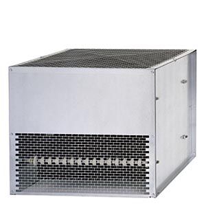
Braking resistors
- Заказные данные (1)
- Информационные материалы
Информационные материалы
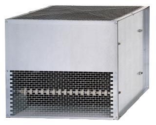
Braking resistor
Excess energy in the DC link is dissipated in the braking resistor.
The braking resistor is connected to the Braking Module. The braking resistor is positioned outside the cabinet or switchgear room. This enables the resulting heat loss to be removed from the area of the Power Modules. The level of air conditioning required is therefore reduced.
A temperature switch (NC contact) is fitted. This responds when the maximum permissible temperature is exceeded and can be evaluated by a controller. The maximum permissible cable length between the Braking Module and braking resistor is 100 m.
Характеристика
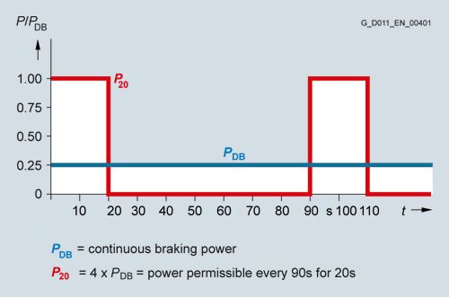
Load diagram for Braking Modules and braking resistor
Технические данные
Line voltage 380 V ... 480 V 3 AC
Braking resistor
6SE7032-5FS87-2DC0
Resistance
3.1 Ω (± 10 %)
Rated power PDB
(Continuous braking power)
50 kW
Power P20
200 kW
Current, max.
378 A
Cable connections
M12 stud
- Power cable, max.
70 mm2
- PE/GND, max.
50 mm2
Cable length to Braking Module, max.
≤100 m
Degree of protection
IP20
Dimensions
- Width
740 mm
- Height
1325 mm
- Depth
485 mm
Weight, approx.
109 kg
Suitable for Braking Module
6SL3760-1AE32-6AA0