
- Каталог оборудования Siemens
- Каталог продуктов Siemens Industry
- Приводная техника
- Преобразователи
- Стандартные преобразователи
- Общая информация о базовых преобразователях SINAMICS V
- Преобразователи частоты общего назначения SINAMICS G
- Преобразователи частоты SINAMICS G110
- Компактные преобразователи SINAMICS G120C
- Преобразователи для насосов, вентиляторов,компрессоров SINAMICS G120P
- Обзор
- Введение
- Преобразователи для насосов, вентиляторов, компрессоров SINAMICS G120P
- Integrated Drive Systems
- SINAMICS G120P, built-in and wall-mounted units, IP20/IP54/IP55
- SINAMICS G120P Cabinet, cabinet units, IP20 to IP54
- Selection and engineering tools
- Инженерные инструменты
- Services and documentation
- Инструменты проектирования
- Сервис и документация
- Стандартные преобразователи SINAMICS G120
- SINAMICS G110M distributed inverters
- Преобразователь частоты SINAMICS G110D для распределенной периферии
- Преобразователи частоты SINAMICS G120D
- Преобразователи SINAMICS G130 формат шасси
- Преобразователь частоты SINAMICS G150 шкафного исполнения
- SINAMICS G180
- Высокопроизводительные преобразователи SINAMICS S
- MICROMASTER
- SIPLUS POSMO A
- SIMODRIVE POSMO
- LOHER DYNAVERT Drive System
- Преобразователи на среднее напряжение
- Преобразователи постоянного тока
- Стандартные преобразователи
- Двигатели переменного тока
- Generators
- Мотор-редукторы
- Flender Gear Units
- Couplings
- Инструментальное программное обеспечение
- Дополнительные компоненты
- Преобразователи
- Техника автоматизации
- Energy
- Автоматизация и безопасность зданий
- Низковольтная коммутационная техника
- Технология безопасности
- Системные решения и продукты для отраслей
- Сервис
- Приводная техника
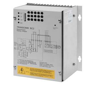
Braking Modules
- Заказные данные (1)
- Информационные материалы
Информационные материалы
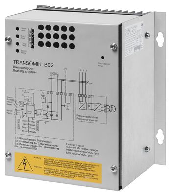
Braking Module
A Braking Module and the matching braking resistor are needed by the drive when it brakes or needs to be stopped for a specific reason, e.g. for an EMERGENCY STOP. Large fans which are caused to rotate by air flow are a typical application. In such instances, it is important to consider operating states which could result in speeds in excess of the desired maximum speed but also the possibility of reversal of rotational direction during restart from standstill. A braking unit is also required if the fan must be brought to a standstill within a defined time period.
The Braking Module houses the power electronics and the associated control circuit. The supply voltage for the electronics is taken from the DC link.
During operation, the DC link power is converted into heat loss in an external braking resistor.
The activation threshold of the Braking Module can be adjusted by means of a switch. The braking power values indicated in the technical specifications apply to the upper activation threshold.
Дизайн
The Braking Module is designed for installation in the control cabinet. It must always be mounted vertically.
A Braking Module is assigned its own dedicated braking resistor. The Braking Module is connected to the DC link by means of flexible cables.
The Braking Module has the following interfaces as standard:
- DC link connection
- Connection for braking resistor
- 1 digital input (inhibit Braking Module/reset error)
- 1 digital output (Braking Module faulty/ready)
A switch is provided for adjusting the activation threshold.
Характеристика
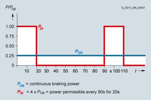
Load diagram for Braking Modules and braking resistor
Интеграция
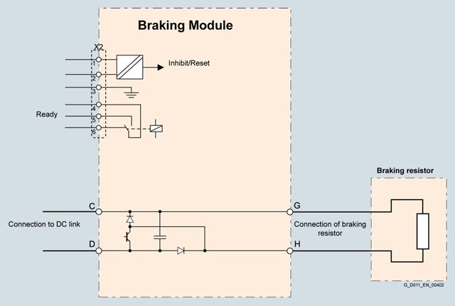
Connection example of a Braking Module
Технические данные
Line voltage 380 ... 480 V 3 AC
Braking Module
6SL3760-1AE32-6AA0
Rated power PDB
50 kW
Power P20
200 kW
Braking current for PDB
65 A
Activation thresholds
(adjustable via switch)
670 V / 770 V (factory setting)
Connectable resistance
- With braking power PDB
3.1 Ω
Digital input
- Voltage
24 V
- Low level
(an open digital input is interpreted as "low")
<3 V
- High level
<7 V
- Current consumption at 24 V DC, typ.
0.01 mA
- Conductor cross-section, max.
2.5 mm2
Digital output
- AC voltage, max.
250 V
- Load current per digital output, max.
2 A
- Conductor cross-section, max.
2.5 mm2
Power loss, max.
0.1 kW
Braking resistor connection
Screw terminal
- Conductor cross-section, max.
35 mm2
- Cable length, max.
100 m
DC link connection
Screw terminal
- Conductor cross-section, max.
35 mm2
- Cable length, max.
3 m
Degree of protection
IP20
Dimensions
- Width
180 mm
- Height
220 mm
- Depth
152 mm
Weight, approx.
5.5 kg