
- Каталог оборудования Siemens
- Каталог продуктов Siemens Industry
- Приводная техника
- Техника автоматизации
- Системы автоматизации
- Системы визуализации SIMATIC HMI
- Системы идентификации
- Промышленные коммуникации SIMATIC NET
- Промышленные аппараты управления SIRIUS
- Промышленные информационные технологии
- Управление на базе РС
- Системы управления процессом
- Контрольно-измерительные приборы
- Измерительные преобразователи для давления
- Transmitter for rel. pressure, abs. pressure, diff. pressure, flow and level
- Измерительные преобразователи для любых применений во всех отраслях промышленности
- Преобразователь для работы по протоколу WirelessHART
- Преобразователи давления для пищевой, фармацевтической промышленностей и биотехнологий
- Преобразователи давления для бумажной промышленности
- Преобразователи общего назначения
- Измерительные преобразователи для применений с повышенными тебованиями
- Высокоэффективные измерительные преобразователи
- SITRANS P разделители давления (HID: print)
- Фитинги
- Transmitter for rel. pressure, abs. pressure, diff. pressure, flow and level
- Приборы измерения температуры SITRANS T
- Расходомеры
- Уровнемеры
- Позиционеры
- Устройство для защиты и пуска двигателей SIMOCODE-DP
- Сигнализаторы сбоев в промышленном процессе
- Аппаратные ПИД-регуляторы SIPART
- Встраиваемые самописцы и индикаторы
- Технологии взвешивания
- Дополнительные компоненты
- Коммуникации и программное обеспечение
- Directives
- Измерительные преобразователи для давления
- Анализаторы процесса
- Блоки питания SITOP
- Продукты для специальных требований
- Energy
- Автоматизация и безопасность зданий
- Низковольтная коммутационная техника
- Технология безопасности
- Системные решения и продукты для отраслей
- Сервис
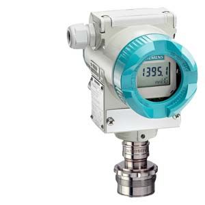
SITRANS P DS III with PMC connection
- Заказные данные (3)
- Информационные материалы
Чертеж

SITRANS P DS III pressure transmitters for gauge pressure, with PMC connection, dimensions in mm (inch)
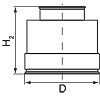
The diagram shows a SITRANS P DS III with an example of a flange. In this drawing the height is subdivided into H1 and H2.
H1 = Height of the SITRANS P DS III up to a defined cross-section
H2 = Height of the flange up to this defined cross-section
Only the height H2 is indicated in the dimensions of the flanges.
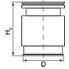
PMC Style standard weldable sockets
PMC Style minibolt weldable sockets
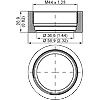
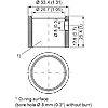
PMC Style Standard (left) and PMC Style Minibolt (right) weldable sockets, dimensions in mm (inch)
Material: Stainless steel, Mat. No. 1.4404/316L
PMC Style standard
DN
PN
∅D
H2
40.9 mm (1.6")
approx. 36.8 mm (1.4")
PMC Style minibolt
DN
PN
∅D
H2
26.3 mm (1.0")
approx. 33.1 mm (1.3")
Технические данные
SITRANS P, DS III series for gauge pressure with PMC connection for the paper industry
Input
Measured variable
Gauge pressure
Span (fully adjustable) or nominal measuring range, max. operating pressure and max. test pressure
HART
PROFIBUS PA and FOUNDATION Fieldbus
Span
Nominal measuring range
Max. perm. operating pressure MAWP (PS)
Max. permissible test pressure
0.01 ... 1 bar
1 ... 100 kPa
0.15 ... 14.5 psi1 bar
100 kPa
14.5 psi4 bar
400 kPa
58 psi6 bar
600 kPa
87 psi0.04 ... 4 bar
4 ... 400 KPa
0.58 ... 58 psi4 bar
400 KPa
58 psi7 bar
0.7 MPa
102 psi10 bar
1 MPa
145 psi0.16 ... 16 bar
16 .... 1600 kPa
2.32 ... 232 psi16 bar
1600 kPa
232 psi21 bar
2.1 MPa
305 psi32 bar
3.2 MPa
464 psiLower measuring limit
(for PMC Style Minibolt no span < 500 mbar adjustable)100 mbar a/10 kPa a/1.45 psia
Upper measuring limit
100 % of max. span
Output
HART
PROFIBUS PA and FOUNDATION Fieldbus
Output signal
4 ... 20 mA
Digital PROFIBUS PA and FOUNDATION Fieldbus signal
- Lower limit (fully adjustable)
3.55 mA, factory preset to 3.84 mA
-
- Upper limit (fully adjustable)
23 mA, factory preset to 20.5 mA or optionally set to 22.0 mA
-
Load
- Without HART
RB ≤ (UH - 10.5 V)/0.023 A in Ω,
UH: Power supply in V-
- With HART
RB = 230 ... 500 Ω (SIMATIC PDM) or
RB = 230 ... 1100 Ω (HART Communicator)-
Physical bus
-
IEC 61158-2
Protection against polarity reversal
Protected against short-circuit and polarity reversal. Each connection against the other with max. supply voltage.
Electrical damping (step width 0.1 s)
Set to 2 s (0 ... 100 s)
Measuring accuracy
According to IEC 60770-1
Reference conditions
- Rising characteristic curve
- Start of scale 0 bar
- Seal diaphragm stainless steel
- Silicone oil filling
- Room temperature (25 °C (77 °F))
Measuring span ratio r (spread, Turn-Down)
r = maximum measuring span/set measuring span or nominal measuring range
Error in measurement at limit setting including hysteresis and reproducibility
- Linear characteristic
- r ≤ 5
≤ 0.075 %
- 5 < r ≤ 100
≤ (0.005 · r + 0.05) %
Effect of ambient temperature
≤ (0.08 · r + 0.16) %
Long-term stability (temperature change ±30 °C (±54 °F))
≤ (0.25 · r) % in 5 years
Influence of mounting position
≤ 0.1 mbar/0.01 kPa/0.00145 psi per 10° incline (zero point correction is possible with position error compensation)
Effect of auxiliary power (in percent per voltage change)
0.005 % per 1 V
Measured-value resolution for PROFIBUS PA and FOUNDATION Fieldbus
3 · 10-5 of nominal measuring range
Rated conditions
Degree of protection according to IEC 60529
IP66 (optional IP66/IP68), NEMA 4X
Temperature of medium
-40 ... +100 °C (-40 ... +212 °F)
Ambient conditions
- Ambient temperature
- Transmitter
(with 4-wire connection, observe temperature values of supplementary 4-wire electronics)
-40 ... +85 °C (-40 ... +185 °F)
- Storage temperature
-50 ... +85 °C (-58 ... +185 °F)
- Climatic class
- Condensation
Relative humidity 0 ... 100 %
Condensation permissible, suitable for use in the tropics- Electromagnetic compatibility
- Emitted interference and interference immunity
According to IEC 61326 and NAMUR NE 21
Design
Weight (without options)
≈ 1.5 kg (≈ 3.3 lb)
Enclosure material
Low-copper die-cast aluminum, GD-AlSi 12 or stainless steel precision casting, mat. no. 1.4408
Wetted parts materials
- Gasket (standard)
PTFE flat gasket
- O-ring (minibolt)
FPM (Viton) or optionally: FFPM or NBR
Measuring cell filling
Silicone oil or inert fill fluid
Process connection (standard)
Flush-mounted, 1½", PMC Standard design
Process connection (minibolt)
Flush-mounted, 1", minibolt design
Power supply UH
HART
PROFIBUS PA and FOUNDATION Fieldbus
Terminal voltage on transmitter
10.5 ... 45 V DC
10.5 ... 30 V DC in intrinsically-safe mode-
Auxiliary power
-
Bus-powered
Separate supply voltage
-
Not necessary
Bus voltage
- Not Ex
-
9 ... 32 V
- With intrinsically-safe operation
-
9 ... 24 V
Current consumption
- Basic current (max.)
-
12.5 mA
- Start-up current ≤ basic current
-
Yes
- Max. current in event of fault
-
15.5 mA
Fault disconnection electronics (FDE) available
-
Yes
Certificates and approvals
Classification according to pressure equipment directive (PED 2014/68/EU)
For gases of fluid group 1 and liquids of fluid group 1; complies with requirements of article 4, paragraph 3 (sound engineering practice)
1) Conversion of temperature error per 28 °C. Valid for temperature range -3 ... +53 °C < (0.064 . r + 0.08) %/28 °C (50 °F).
HART communication
HART
230 ... 1100 Ω
Protocol
HART Version 5.x
Software for computer
SIMATIC PDM
PROFIBUS PA communication
Simultaneous communication with master class 2 (max.)
4
The address can be set using
Configuration tool or local operation (standard setting address 126)
Cyclic data usage
- Output byte
5 (one measured value) or
10 (two measured values)- Input byte
0, 1, or 2 (register operating mode and reset function for metering)
Internal preprocessing
Device profile
PROFIBUS PA Profile for Process Control Devices Version 3.0, Class B
Function blocks
2
- Analog input
- Adaptation to user-specific process variable
Yes, linearly rising or falling characteristic
- Electrical damping adjustable
0 … 100 s
- Simulation function
Input /Output
- Failure mode
parameterizable (last good value, substitute value, incorrect value)
- Limit monitoring
Yes, one upper and lower warning limit and one alarm limit respectively
- Register (totalizer)
Can be reset, preset, optional direction of counting, simulation function of register output
- Failure mode
parameterizable (summation with last good value, continuous summation, summation with incorrect value)
- Limit monitoring
One upper and lower warning limit and one alarm limit respectively
- Physical block
1
Transducer blocks
2
- Pressure transducer block
- Can be calibrated by applying two pressures
Yes
- Monitoring of sensor limits
Yes
- Specification of a container characteristic with
Max. 30 nodes
- Square-rooted characteristic for flow measurement
Yes
- Gradual volume suppression and implementation point of square-root extraction
Parameterizable
- Simulation function for measured pressure value and sensor temperature
Constant value or by means of parameterizable ramp function
FOUNDATION Fieldbus communication
Function blocks
3 function blocks analog input, 1 function block PID
- Analog input
- Adaptation to user-specific process variable
Yes, linearly rising or falling characteristic
- Electrical damping adjustable
0 … 100 s
- Simulation function
Output/input (can be locked within the device with a bridge)
- Failure mode
parameterizable (last good value, substitute value, incorrect value)
- Limit monitoring
Yes, one upper and lower warning limit and one alarm limit respectively
- Square-rooted characteristic for flow measurement
Yes
- PID
Standard FOUNDATION Fieldbus function block
- Physical block
1 resource block
Transducer blocks
1 transducer block Pressure with calibration, 1 transducer block LCD
- Pressure transducer block
- Can be calibrated by applying two pressures
Yes
- Monitoring of sensor limits
Yes
- Simulation function: Measured pressure value, sensor temperature and electronics temperature
Constant value or by means of parameterizable ramp function