
- Каталог оборудования Siemens
- Каталог продуктов Siemens Industry
- Приводная техника
- Техника автоматизации
- Системы автоматизации
- Системы визуализации SIMATIC HMI
- Системы идентификации
- Промышленные коммуникации SIMATIC NET
- Промышленные аппараты управления SIRIUS
- Промышленные информационные технологии
- Управление на базе РС
- Системы управления процессом
- Контрольно-измерительные приборы
- Анализаторы процесса
- Блоки питания SITOP
- Продукты для специальных требований
- Energy
- Автоматизация и безопасность зданий
- Низковольтная коммутационная техника
- Технология безопасности
- Системные решения и продукты для отраслей
- Сервис
General information
- Информационные материалы
Информационные материалы
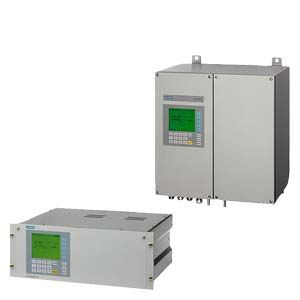
The CALOMAT 62 gas analyzer is primarily used for quantitative determination of one gas component (e.g. H2, N2, Cl2, HCl, NH3) in binary or quasi-binary gas mixtures.
The CALOMAT 62 is specially designed for use in corrosive gas mixtures.
Область применения
Fields of application
- Chlorine-alkali electrolysis
- Metallurgy (steel production and processing)
- H2 measurement in LNG (Liquefied Natural Gas) process
- Ammonia synthesis
- Fertilizer production
- Petrochemicals
Special versions
Special applications
In addition to the standard combinations, special applications are also available upon request (e.g. higher sample gas pressure up to 2 000 hPa absolute).
Дизайн
19" rack unit
- With 4HE for installation
- in hinged frame
- in cabinets with or without telescope rails
- With closed or flow-type reference chambers
- Front plate for service purposes can be pivoted down (laptop connection)
- IP20 degree of protection, with purging gas connection
- Internal gas routes: Pipe made of stainless steel (mat. no. 1.4571)
- Gas connections for sample gas inlet and outlet and for reference gas: Internal thread 1/8" – 27 NPT
- Purging gas connections: Pipe diameter 6 mm or 1/4"
- With closed or flow-type reference chambers
Field device
- Two-door enclosure (IP65) for wall mounting with gas-tight separation of analyzer and electronic parts, purgeable
- Individually purgeable enclosure halves
- Gas path with screw pipe connection made of stainless steel (mat. no. 1.4571), or Hastelloy C22
- Purging gas connections: Pipe diameter 10 mm or 3/8"
- Gas connections for sample gas inlet and outlet and for reference gas: Internal thread 1/8" – 27 NPT
- With closed or flow-type reference chambers
Display and control panel
- Large LCD field for simultaneous display of:
- Measured value (digital and analog displays)
- Status bar
- Measuring ranges
- Contrast of the LCD field adjustable via the menu
- Permanent LED backlighting
- Washable membrane keyboard with five softkeys
- Menu-driven operator control for parameterization, test functions, adjustment
- Operator support in plain text
- Graphical display of the concentration progression; time intervals parameterizable
- Bilingual operating software German/English, English/Spanish, French/English, Spanish/English, Italian/English
Input and outputs
- One analog output per medium (from 0, 2, 4 to 20 mA; NAMUR parameterizable)
- Two analog inputs configurable (e.g. correction of cross-interference or external pressure sensor)
- Six binary inputs freely configurable (e.g. measurement range changeover, processing of external signals from the sample preparation)
- Six relay outputs, freely configurable (e.g. failure, maintenance request, threshold alarm, external magnetic valves)
- Each can be expanded by eight additional binary inputs and relay outputs (e.g. for autocalibration with max. four test gases)
Communication
RS 485 present in basic unit (connection from the rear; for the rack unit also behind the front plate).
Options
- RS 485/RS 232 converter
- RS 485/Ethernet converter
- RS 485/USB converter
- Connection to networks via PROFIBUS DP/PA interface
- SIPROM GA software as the service and maintenance tool
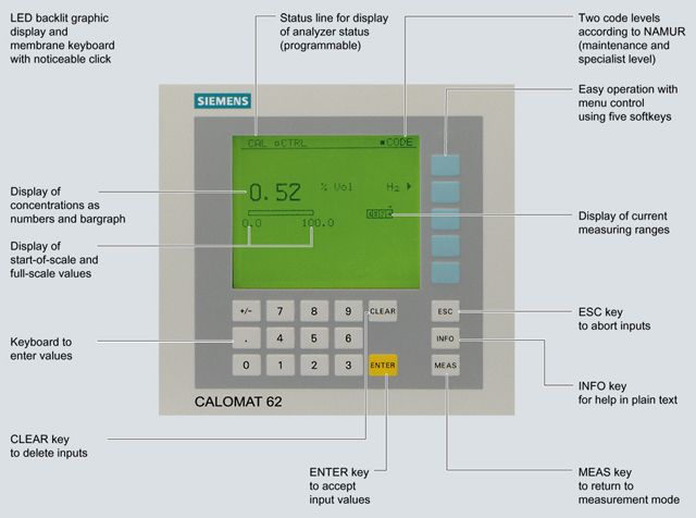
CALOMAT 62, membrane keyboard and graphic display
Designs – parts wetted by sample gas
Gas connection
19" rack unit
Field device
Input block with gas connection
Stainless steel, mat. no. 1.4571
Stainless steel, mat. no. 1.4571
Seal
FPM (e.g. Viton) or FFPM
FPM (e.g. Viton) or FFPM
Sensor
Glass
Glass
Input block with gas connection
Hastelloy C22
Seal
FFPM (e.g. Kalrez)
Sensor
Glass
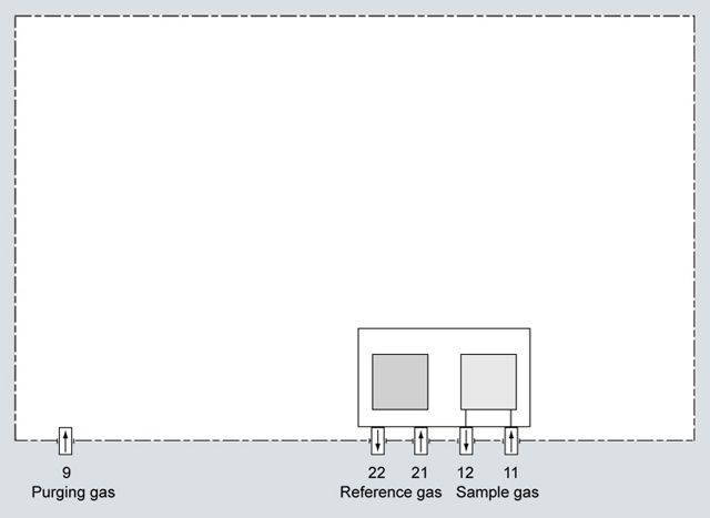
CALOMAT 62, 19" rack unit, gas path
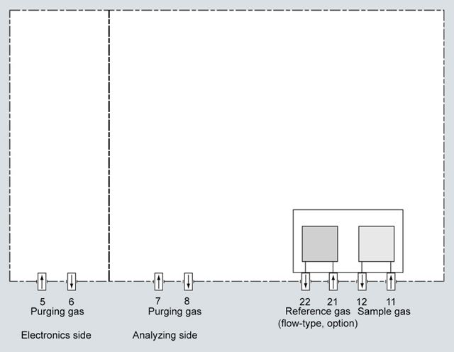
CALOMAT 62, field device, gas path
Функции
Principle of operation
The measuring principle is based on the different thermal conductivity of gases.
The temperature of a heated resistor surrounded by gas is determined by the thermal conductivity of the gas. Four such resistors are connected as a bridge.
Sample gas flows around two of them, reference gas surrounds the other two. A constant DC voltage heats the resistors above the temperature of the measurement block.
The different thermal conductivities of the sample and reference gases result in different temperatures of the resistors. A change in the composition of the sample gas thus also causes a change in the resistance values.
The electrical equilibrium of the measuring bridge is disrupted, and a voltage is generated in the bridge diagonal. This is a measure of the concentration of the measured component.
Note
The sample gases must be fed into the analyzers free of oil, grease, and dust. The formation of condensation in the sample chambers (dew point of sample gas < ambient temperature) must be avoided. Therefore, gas prepared for the respective task must be provided in most applications.
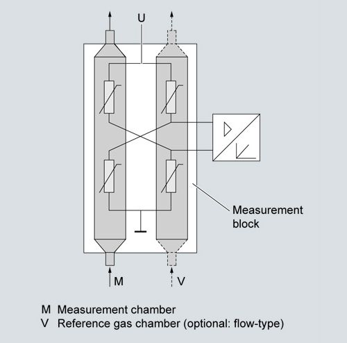
CALOMAT 62, principle of operation, example of a non-flow-type reference chamber
Important features
- Four freely-programmable measuring ranges, also with suppressed zero, all ranges linear
- Smallest spans down to 1 % H2 (with suppressed zero: 99 to 100 % H2) possible
- Measuring range identification
- Electrically isolated measured-value output 0/2/4 to 20 mA (also inverted)
- Automatic or manual measuring range switchover selectable; remote switching is also possible
- Measured value can be saved during adjustment
- Time constants are selectable within wide ranges (static/dynamic noise suppression); i.e. the response time of the analyzer can be adapted to the respective task
- Short response time
- Low long-term drift
- Measuring point switchover for up to 6 measuring points (parameterizable)
- Measuring point identification
- External pressure sensor can be connected – for correction of variations in sample gas pressure
- Possibility for correcting the influence of residual gases (correction of cross-interference)
- Automatic measuring range calibration can be programmed
- Operation based on the NAMUR recommendation
- Two operator input levels with their own authorization codes to prevent unintentional and unauthorized interventions
- Simple handling using a numerical membrane keyboard and operator prompting
- Customer-specific device versions, such as:
- Customer acceptance
- TAG labels
- Drift recording
- Clean for O2 service
Spans
The smallest and largest possible spans depend on both the measured component (gas type) and the respective application (see ordering data).
Cross-interferences
Information on the sample gas composition is required in order to determine the cross-interference of residual gases with several interfering components.
The zero offsets in % H2 which result from 1 % residual gas (interfering gas) are listed in the following table; the specified values are approximate values.
It should be noted that the influence of interfering gas is not linear to its concentration. Information on the sample gas composition is required in order to determine the cross-interference of residual gases with several interfering components.
Ar
Approx. - 0.15 %
O2
Approx. + 0.02 %
CO2
Approx. - 0.13 %
CH4
Approx. + 0.17 %
SO2
Approx. - 0.31 %
Air (dry)
Approx. + 0.25 %
Effect of 1 % gas component with nitrogen as the residual gas, expressed in % H2
Moreover, it must be noted that - in addition to a zero offset - the gradient of the characteristic can also be affected by the residual gas. However, this effect is negligible in the case of variations in the interfering gas concentration below 10 %.
Taking these facts into consideration and due to the fact that the cross-interference analyzers cause further measuring inaccuracies, a larger error in measurement occurs than with digital gas mixtures despite correction of cross-interference.
Specification for the interface cable
Surge impedance
100 ... 300 Ω, with a measuring frequency of > 100 kHz
Cable capacitance
Typ. < 60 pF/m
Core cross-section
> 0.22 mm2, corresponds to AWG 23
Cable type
Twisted pair, 1 x 2 conductors of cable section
Signal attenuation
Max. 9 dB over the whole length
Shielding
Copper braided shield or braided shield and foil shield
Connection
Pin 3 and pin 8
Bus terminating resistors
Pins 3-7 and 8-9 of the first and last connectors of a bus cable must be bridged (see graphic).
Note
It is advisable to install a repeater on the device side in the case of a cable length of more than 500 m or with high interferences.
Up to four components can be corrected via the ELAN bus, correction of cross-interference can be carried out for one or two components via the analog input.
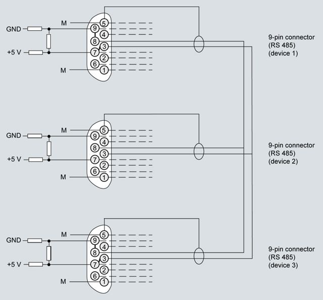
Bus cable with plug connections, example
Особенности
- Universally applicable hardware basis
- Integrated correction of cross-interference, no external calculation required
- Open interface architecture (RS 485, RS 232, PROFIBUS)
- SIPROM GA network for maintenance and servicing information (option)
- Electronics and analyzer unit: gas-tight isolation, purging is possible, IP65, long service life even in harsh environments (field device)