
- Каталог оборудования Siemens
- Каталог продуктов Siemens Industry
- Приводная техника
- Техника автоматизации
- Системы автоматизации
- Системы визуализации SIMATIC HMI
- Системы идентификации
- Промышленные коммуникации SIMATIC NET
- Промышленные аппараты управления SIRIUS
- Промышленные информационные технологии
- Управление на базе РС
- Системы управления процессом
- Контрольно-измерительные приборы
- Анализаторы процесса
- Блоки питания SITOP
- Продукты для специальных требований
- Energy
- Автоматизация и безопасность зданий
- Низковольтная коммутационная техника
- Технология безопасности
- Системные решения и продукты для отраслей
- Сервис
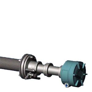
Cross-duct sensor CD 6
- Заказные данные (1)
- Аксессуары (4)
- Информационные материалы
Информационные материалы
Cross-duct sensors CD 6 and cables for non-Ex applications
The standard cross-duct sensor consists of a transmitter unit and a detector unit with the same dimensions. The transmitter unit provides a connector for the fiber-optic cable. The laser light is transmitted through this cable. The receiver unit contains a photodetector and an electronics PCB, and is connected to the detector unit by a sensor cable.
The sensors are mounted onto flanges. The easiest way to avoid condensation and dust deposits on the sensor windows is to use a purging gas, e.g. with instrument air. Purging must be selected depending on the application. The cross-duct sensors can therefore be configured for the respective situation. The application reference table provides recommendations for suitable purging with standard applications.
If a component is to be measured which is also present in measurable quantities in the purging medium - such as oxygen or moisture - it is necessary to use purging gases such as nitrogen, superheated process steam or similar. In such cases it is usually also necessary to purge the sensor heads, since the ambient air must also be displaced here out of the laser beam path. A differentiation is therefore made between purging on the process side and purging on the sensor side.
Note: For measurement of O2 at gas temperatures above 600 °C, it may also be possible to tolerate air as the purging medium since its influence on the measurement can be compensated.
Applications with oxygen (high-pressure)
For oxygen measurements with a higher process gas pressure (1 to 5 bar), the sensor CD 6 can be used together with a high-pressure window flange as the process connection. This window flange is also available in the standard sizes DN 65/PN 6, DN 80/PN 16 or ANSI 4"/150 lbs. The optical surface to the process is made of borosilicate glass. High-pressure window flanges can be equipped with window purging, but without purging tubes. Possible purge modes for the window flanges are "A-C" (no purging or moderate purging on the process side). Window flanges are tested for leakage before delivery using overpressure, and show leakage rates of less than 10-5 mbar·l/s.
For ordering this application, the MLFB code of the central unit with the application code letter "P" must be selected. The process interface suitable for the sensors can be chosen by selection of the corresponding code in the 6th configurable position of the MLFB number.
The most important sensor purging configurations are presented below:
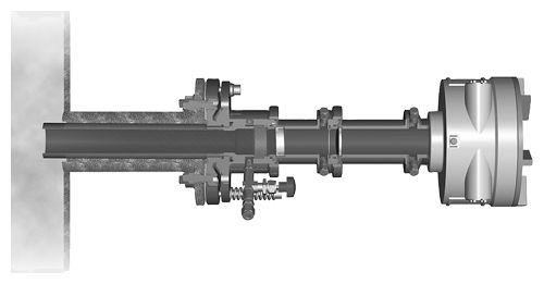
Purging on the process side with moderate flow
Selected for pure gas applications, emission monitoring, inertia monitoring, for example. The purging gas flow can be adjusted between 0 and approx. 120 l/min at each sensor head using a needle valve (included in delivery).
Moderate purging on the process side
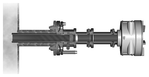
Purging on the process side with increased flow
Through omission of needle valve. This type of purging is selected in crude gas applications with higher concentrations of particles and/or condensation as well as in non-purified flue gases in combustion plants. The purging gas flow is typically set between 200 and 500 l/min on each sensor head depending on the input pressure of the purging medium.
Increased purging on the process side
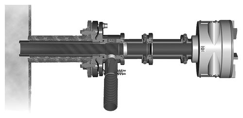
Purging on the process side with high flow
Through use of air blower or dry process steam. Connectors with hose adapters are included in the delivery. An additional Swagelok adapter must be ordered if a high flow of steam or instrument air purging is required (option A27). This type of purging is selected in crude gas applications with very high concentrations of particles and/or condensation such as in the furnaces of combustion plants. If instrument air is not available, an air blower is also an alternative for purging in applications with lower demands. On the process side, dry steam can be used as the inert purging gas instead of nitrogen (Tmax. 240 °C). The purging gas flow is automatically set between 500 and <1 000 l/min on each sensor head depending on the purging air blower or the steam pressure.
Increased purging on the process side, with hose connection adapter
Purging on sensor side
Can be combined with any purging mode on the process side, and is always selected if the ambient air must never have an influence on the measurement. The volumes within the sensor head are then continuously purged with an O2-free gas (with H2O-free gas in the case of moisture measurement).
Note
With purging on the process side, it may be necessary to use non-return valves to ensure no process gas can enter the purging gas line in the event of failure of the purging gas supply. This applies especially in the case of cascaded process and sensor purging where there is otherwise the danger that, for example, corrosive process gases could enter the sensor enclosure.
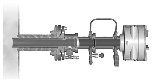
Sensor configuration with high purging on the process side, with 6 mm joint for use with steam, and with N2 purging on the sensor side
The purging media used on the process side flow through purging gas tubes into the process gas flow. The tubes extend a few centimeters into the process area, and usually receive a flow of process gas from the side. This results in a wedge being generated in the inlet zone of the purging gas. The effective measuring path in the process gas is therefore well-defined as the distance between the ends of the two purging gas inlet tubes.
Cross-duct sensor CD 6: Options and accessories
Sensor alignment kit
Includes a battery-operated visible light source, a centering aid with crosshair, and two hook spanners for opening the optics tube of the sensors.
Please note: the sensor alignment kit is not explosion protected.
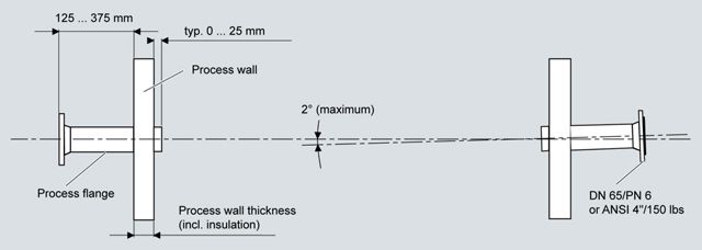
Installation requirements for the cross-duct sensors CD 6, dimensions in mm
Purging air blower
Two purging air blowers are required to purge the sensor heads. Both 230 V AC and 115 V AC versions can be ordered.
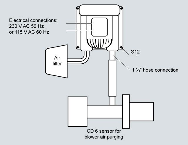
Sensor configuration with purging air blower
Flow cell (available on special application)
For implementation of measuring configurations with bypass mode. The cell consists of a stainless steel tube whose internal surfaces are coated with PTFE to minimize surface effects. With an effective measuring path of 1 m, the inner volume is only 1.2 l, and fast gas displacement times can therefore be achieved. The flow of sample gas can be from the ends or from the center of the tube, since appropriate 6 mm joints are present here. The flow cell can be ordered in four configurations:
- Unheated, including assembly for wall mounting
- Unheated, including assembly for wall mounting and a 19" housing with an air jet pump with a delivery rate of max. 30 l/min
- As above, but can be heated up to approx. 200 °C
- As above, but can be heated up to approx 200 °C and mounted on a rack with wheels and integrated 19" frame
Optical bandpass filter (only for O2-CD 6)
Serves to protect the light-sensitive detector in the receiver unit of the sensor from saturation by IR background radiation. Used with measurements in very hot process gases (T > 1 000 °C) or with unavoidable appearances of flames in the measurement path.
Чертеж
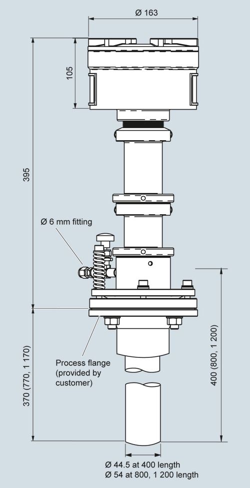
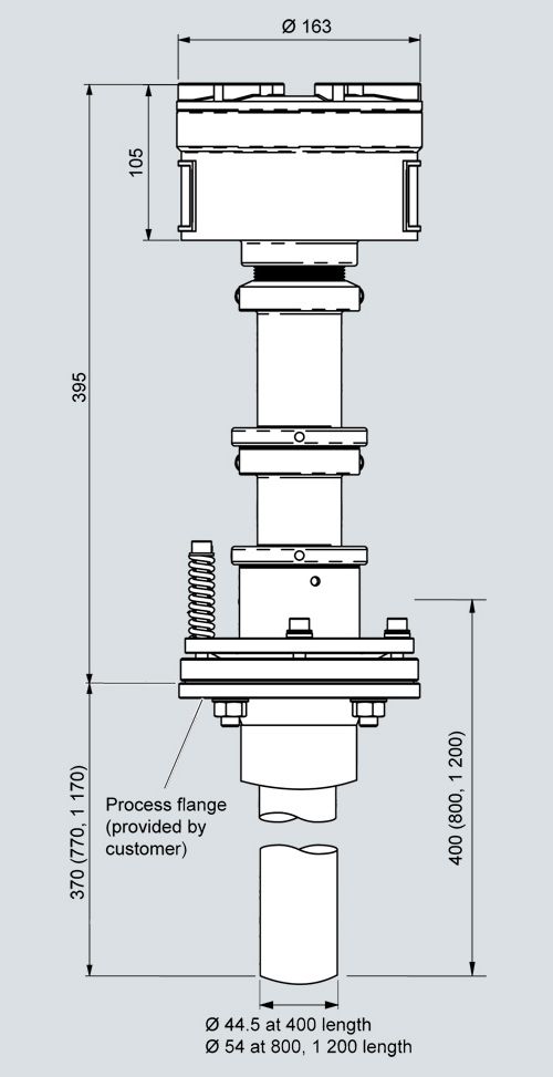
Cross-duct sensor CD 6, moderate purging (instrument air), version according to Order No. 7MB6122-**C1*-0***, dimensions in mm
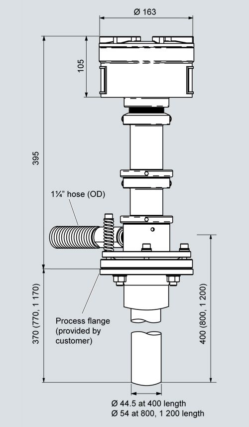
Cross-duct sensor CD 6, increased purging (instrument air), version according to Order No. 7MB6122-**E1*-0***, dimensions in mm
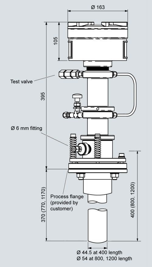
Cross-duct sensor CD 6, blower purging, version according to Order No. 7MB6122-**G1*-0***, dimensions in mm
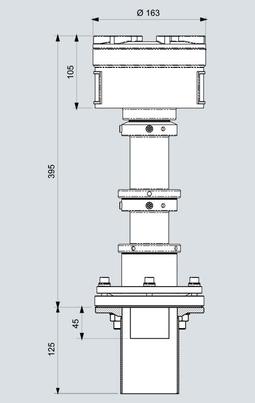
Cross-duct sensor CD 6, sensor and process side purging, version according to Order No. 7MB6122-**H1*-0***-Z A27, dimensions in mm
Cross-duct sensor CD 6, purged version according to Order No. 7MB6122-*WC14-2***, dimensions in mm
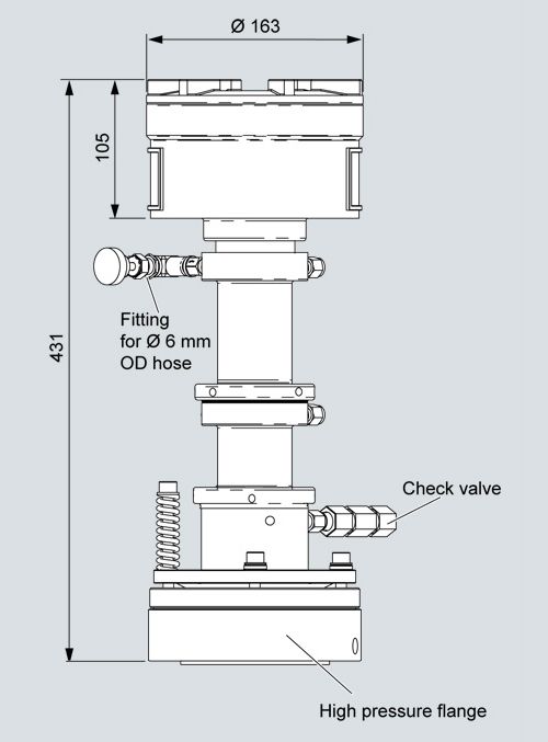
CD 6 high-pressure sensor for oxygen, dimensions in mm
Технические данные
Cross-duct sensor CD 6
General information
Design
Transmitter and detector units, connected by a sensor cable
Materials
Stainless steel (1.4305/303), aluminum
Installation
Vertical or parallel to the gas flow
Laser protection class
Class 1, safe to the eye
Explosion protection
II 1 G Ex ia op to IIC T4 Ga
II 1 D Ex ia op to IIIC T135 °C DaA defined leak rate can only be guaranteed when using high-pressure window flanges. Otherwise, it may be necessary for the owner to carry out an evaluation in accordance with ATEX
DEMKO 06 ATEX 139648X;
IECEx UL 13.0029XDesign, enclosure
Degree of protection
IP65
Dimensions
Diameter: 163, L: 450 mm
Purging gas tube in mm
400 (370 net) x 44 x 40
800 (770 net) x 54 x 40
1 200 (1 170 net) x 54 x 40Weight
2 x approx. 11 kg
Mounting
DN 65/PN 6, DN 80/PN 16 or ANSI 4"/150 lbs
Please note:
- For purging tubes with a length of 800 and 1 200 mm, the wall thickness must not exceed 200 mm with DN 65/PN 6 connections. To carry out measurements with thicker walls, please contact Siemens.
- The optimum adjustment of the flanges can change with high differences in temperature between the process and environment depending on the type of assembly.
Electrical characteristics
Power supply
24 V DC, supply from central unit via hybrid cable
Power consumption
< 2 W with non-Ex configuration, max. 0.6 W with Ex configuration
Climatic conditions
Sensor temperature
Non-Ex
-20 ... +70 °C in operation
-30 ... +70 °C during transport and storage
Ex
-20 ... +60 °C in operation
-30 ... +70 °C during transport and storage
Humidity
< 95 % RH, above dew point
Pressure
800 ... 1 100 hPa
Temperature range on the sensor side of the process interface (connection plate)
-20 ... +70 °C
Measuring conditions
Measurement path
0.3 ... 12 m (other path lengths on request)
Dust load
The influence of dust is very complex and depends on the path length and particle size. The optical attenuation increases exponentially at longer path lengths. Smaller particles also have a very large influence on the optical attenuation. With high dust load, long path length and small particle size, the technical support at Siemens should be consulted.
Accessories
Purging
Nitrogen is permissible as the purging gas for the sensor side. Nitrogen, steam, air and gases which are not subject to the pressure equipment directive Cat. 2 are permissible as purging gases for the process side.
Purging with instrument air, N2
- Max. overpressure in the sensor
< 500 hPa
- Quality
- Instrument air
According to ISO 8573-1:2010 [2:3:3]
Note: It is sufficient if the pressure condensation point is min. 10 K below the minimum ambient temperature.
- Nitrogen
Purity better than 99.7 %. For oxygen measurements, an O2 content < 0.01% in the purging gas.
Optical path length ≥ 1 m, min. 5% oxygen in the process gas.- Maximum flow rate (process purging)
500 l/min
- Dew point
Benchmark: < -10 °C, condensation on the optics must be avoided
Blower purging
- Maximum counter pressure
40 hPa
- Maximum flow rate
850 l/min
- Power consumption
370 W
- Degree of protection (fan)
IP54, cover required to protect against rain
Steam purging
- Steam conditioning
Overheated
- Maximum temperature
240 °C
- Minimum pressure
> 4 000 hPa
- Maximum pressure
16 000 hPa, refers to a volume flow of approx. 1 100 l/min
Hybrid and sensor cables
General information
Configuration hybrid cable
Two optical fibers and two twisted copper wires in one cable for 24 V DC. Single-mode optical fiber fabricated at both ends with E2000 angle connectors. Multimode optical fiber configured at both ends with SMA connectors.
Cable is flame-retardant, very good resistance to oil, gasoline, acids and alkalis, outer sheath UV-resistant
Cable sheath
Oil-resistant polyurethane
Dimensions
- An external power supply must be additionally ordered for > 500 m
- For installation in hazardous zones, non-intrinsically-safe cables have to be spatially separated from intrinsically-safe lines
- Diameter
< 8.5 mm
- Length
- Use in non-hazardous and Ex Zone 2: Up to 700 m
- Use in Ex Zone 0 and Zone 1: Up to 250 m
Weight
75 kg/km
Maximum tensile force
200 N
Maximum lateral pressure
1 000 N/cm
Impact resistance
200 N/cm
Maximum tensile strength
500 N
Minimum bending radius
12 cm
Climatic conditions
Ambient temperature
-40 ... +70 °C during transport, storage and operation
-5 ... +50 °C during cable installation
Humidity
< 95% rel. humidity, above dew point (in operation and storage)