
- Каталог оборудования Siemens
- Каталог продуктов Siemens Industry
- Приводная техника
- Техника автоматизации
- Energy
- Автоматизация и безопасность зданий
- Низковольтная коммутационная техника
- Технология безопасности
- Системные решения и продукты для отраслей
- Автомобильная промышленность
- Биотопливо
- Химическая промышленность
- Пищевая промышленность
- Производственные машины
- Packaging machines
- Printing presses
- Textile machines
- Converting
- Metal forming technology
- Handling systems
- Непрерывное преобразование листового материала - Converting
- Печать
- Манипуляторы
- Пластик
- Текстиль
- Обработка металлов давлением
- Упаковка
- Компоненты автоматизации для станков
- SINUMERIK 808 with SINAMICS V60/V70
- SINUMERIK 828 with SINAMICS S120
- SINUMERIK 840 with SINAMICS S120
- Introduction SINUMERIK 840D sl with SINAMICS S120
- SINUMERIK CNC control
- SINUMERIK Operate
- SINUMERIK Integrate
- SINAMICS S120 drive system
- SIMOTICS motors
- MOTION-CONNECT connection systems
- Lifecycle Services
- SINUMERIK Solution Partners
- Certificates of suitability (approvals)
- Glossary SINUMERIK 840
- Glossary SINAMICS S120 drive system
- List of abbreviations
- Приводные применения
- Горная и металлургическая промышленность
- Нефтегазовая промышленность
- Фармацевтическая промышленность
- Бумажная промышленность
- Солнечная энергетика
- Транспорт, инфраструктура, логистика
- Вода и водоподготовка
- Сбыт электроэнергии
- Возобновляемые источники энергии
- Отраслевые решения
- Отраслевые продукты
- Сервис
CU310-2 Control Units for single-axis drives
- Заказные данные (11)
- Аксессуары (3)
- Информационные материалы
Информационные материалы
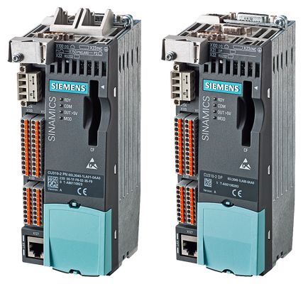
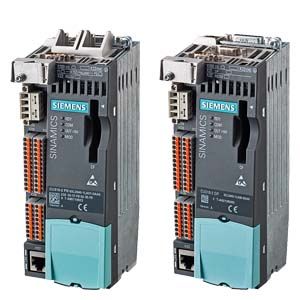
CU310-2 PN and CU310-2 DP Control Units
The CU310‑2 Control Unit that is designed for the communication and open-loop/closed-loop control functions of a SINAMICS S120 (AC/AC) is combined with the PM240‑2 Power Module (can be used from firmware V4.8) to create a high-performance single-axis drive. A PROFINET (PN) variant and a PROFIBUS (DP) variant are available for fieldbus communication.
CompactFlash card for CU310-2 Control Units
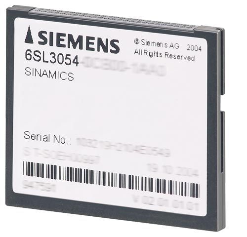
The CompactFlash card contains the firmware and parameter settings. The CompactFlash card is plugged into the appropriate slot on the CU310-2 Control Unit.
A CU310-2 Control Unit can perform the communication, open-loop and closed-loop control functions for one Power Module. The performance expansion is not required in this case.
In addition to the firmware, the CompactFlash Card also contains licensing codes which are required to enable firmware options.
In addition to the Article No., the following firmware options can currently be ordered:
- Safety Integrated Extended Functions, order code F01
- High output frequency 1), order code J01
- DCB Extension, order code U01
After the appropriate license has been purchased via the WEB License Manager available on the Internet, firmware options can also be subsequently enabled.
Further information is available on the Internet at
http://www.siemens.com/automation/license1) For further information, see https://support.industry.siemens.com/cs/document/104020669
Дизайн
The CU310‑2 Control Unit has the following connections and interfaces as standard:
- Fieldbus interface
- CU310‑2 PN: 1 PROFINET interface with 2 ports
(RJ45 sockets) with PROFIdrive V4 profile - CU310‑2 DP: 1 PROFIBUS interface with PROFIdrive V4 profile
- CU310‑2 PN: 1 PROFINET interface with 2 ports
- 1 DRIVE-CLiQ socket for communication with the DRIVE-CLiQ motor or other DRIVE-CLiQ devices (e.g. Sensor Modules or Terminal Modules)
- 1 encoder evaluation for evaluating the following encoder signals
- Incremental encoder TTL/HTL
- SSI encoder without incremental signals
- 1 PE/protective conductor connection
- 1 connection for the electronics power supply via the 24 V DC supply connector
- 1 temperature sensor input for KTY84‑130, Pt1000 or PTC (Pt1000 can be used from firmware V4.7 HF17)
- 3 parameterizable, fail-safe (can be used with firmware V4.5 and higher) digital inputs (floating) or alternatively 6 parameterizable digital inputs (floating).
The fail-safe digital inputs can be routed, i.e. they can be routed via PROFIsafe to a higher-level controller. - 5 parameterizable digital inputs (floating)
- 1 parameterizable, fail-safe (can be used with firmware V4.5 and higher) digital input (floating) or alternatively 1 digital output (floating)1)
- 8 parameterizable bidirectional digital inputs/outputs (non-floating) 1)
- 1 analog input, either ± 10 V (resolution 12 bits + sign) or ± 20 mA (11 bits + sign)
- 1 Ethernet interface (RJ45 socket) for commissioning and diagnostics
- 1 slot for the CompactFlash card on which firmware and parameters are stored
- 1 PM-IF interface for communication with the Power Modules in blocksize format
- 3 test sockets and one reference ground for commissioning support
- 1 interface to the BOP20 Basic Operator Panel
The status of the CU310-2 Control Unit is indicated using multi-color LEDs.
A BOP20 Basic Operator Panel can also be snapped directly onto the CU310‑2 Control Unit for diagnostics.
As the firmware and parameter settings are stored on a plug-in CompactFlash card, the Control Unit can be changed without the need for software tools.
1) A 24 V supply voltage must be connected to terminal X124 for the digital outputs to be used.
Интеграция
The CU310‑2 Control Unit drives Power Modules in blocksize format via the PM‑IF interface. DRIVE‑CLiQ motors or Sensor Modules (SMC) can also be connected to the integrated DRIVE‑CLiQ socket to permit the operation of motors without a DRIVE‑CLiQ interface.
With the BOP20 Basic Operator Panel, parameters can be changed directly on the device. The BOP20 Basic Operator Panel can also be snapped onto the CU310‑2 Control Unit during operation to perform diagnostics.
The CU310‑2 Control Unit and other connected components are commissioned and diagnosed with the STARTER commissioning tool. The CU310‑2 Control Unit requires a CompactFlash card with firmware V4.4 or higher.
A CU310‑2 PN Control Unit communicates with the higher-level control system using PROFINET IO and the PROFIdrive V4 profile.
The SINAMICS S120 drive system with the CU310‑2 PN Control Unit then assumes the function of a PROFINET IO device and can perform the following functions:
- PROFINET IO device
- 100 Mbit/s full duplex
- Supports real-time classes of PROFINET IO:
- RT (Real-Time)
- IRT (Isochronous Real-Time), minimum send cycle 500 μs
- Connects to controls as PROFINET IO devices using PROFIdrive compliant with Specification V4
- Standard TCP/IP communication for engineering processes with the STARTER commissioning tool and for accessing the integrated web server
- Integrated 2‑port switch with two RJ45 sockets based on the ERTEC ASIC. The optimum topology (line, star, tree) can therefore be configured without additional external switches.
A 24 V supply voltage must be connected to terminal X124 for the digital outputs to be used. To operate the CU310‑2 Control Unit, a CompactFlash card with firmware V4.4 or higher is required.
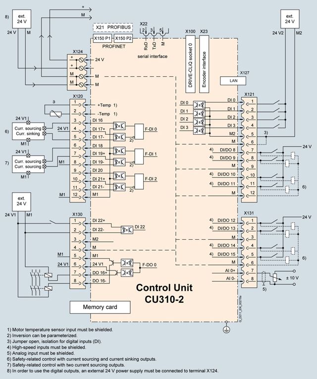
Connection example of CU310‑2 Control Unit
Технические данные
CU310‑2 Control Unit
PROFINET
PROFIBUS6SL3040-1LA01-0AA0
6SL3040-1LA00-0AA0Current requirement, max.
At 24 V DC,
without taking into account the digital outputs and DRIVE‑CLiQ supply0.35 A for CU310‑2 + 0.5 A for PM240‑2 Power Module
Conductor cross-section, max.
2.5 mm2
Fuse protection, max.
20 A
Digital inputs
In accordance with IEC 61131‑2 Type 1
5 floating digital inputs
8 bidirectional non-floating digital inputs/digital outputs
3 parameterizable, fail-safe digital inputs (floating) or alternatively 6 parameterizable digital inputs (floating)
5 bidirectional floating digital inputs/outputs
- Voltage
-3 ... +30 V
- Low level (an open digital input is interpreted as "low")
-3 ... +5 V
- High level
15 ... 30 V
- Current consumption at 24 V DC, typ.
3.5 mA
- Delay time of digital inputs 1), approx.
- L → H
50 μs
- H → L
100 μs
- Delay time of high-speed digital inputs 1), approx.
(high-speed digital inputs can be used for position detection)
- L → H
5 μs
- H → L
50 μs
- Conductor cross-section, max.
1.5 mm2
Digital outputs
(continuously short-circuit proof)
8 bidirectional non-floating digital inputs/digital outputs
- Voltage
24 V DC
- Load current per digital output 2), max.
500 mA
- Delay time 1), typ./max.
- L → H
150 μs/400 μs
- H → L
75 μs/100 μs
- Conductor cross-section, max.
1.5 mm2
Analog input
The analog input can be switched between current input and voltage input
- As voltage input
-10 ... +10 V; Ri > 100 kΩ
Resolution: 12 bits + sign (referred to the maximum range that can be resolved -11 ... +11 V)
- As current input
-20 ... +20 mA; Ri > 250 Ω
Resolution: 11 bits + sign (referred to -22 ... 22 mA)
Max. range that can be resolved: -44 ... +44 mA
Encoder evaluation
- Incremental encoder TTL/HTL
- SSI encoder without incremental signals
- Input impedance
- TTL
570 Ω
- HTL, max.
16 mA
- Encoder supply
24 V DC/0.35 A or 5 V DC/0.35 A
- Encoder frequency, max.
300 kHz
- SSI baud rate
100 ... 250 kBaud
- Resolution absolute position SSI
30 bits
- Cable length, max.
- TTL encoder
100 m (328 ft)
(only bipolar signals permitted) 3)
- HTL encoder
100 m (328 ft) for unipolar signals
300 m (984 ft) for bipolar signals 3)
- SSI encoder
100 m (328 ft)
Power loss
<20 W
PE connection
M4 screw
Dimensions
- Width
73 mm (2.87 in)
- Height
- CU310-2 PN
191 mm (7.52 in)
- CU310-2 DP
187 mm (7.36 in)
- Depth
75 mm (2.95 in)
Weight, approx.
0.95 kg (2.09 lb)
Certificate of suitability
cULus
1) The specified delay times refer to the hardware. The actual reaction time depends on the time slot in which the digital input or output is processed.
2) In order to use the digital outputs, an external 24 V power supply must be connected to terminal X124.
3) Signal cables twisted in pairs and shielded.