
- Каталог оборудования Siemens
- Каталог продуктов Siemens Industry
- Приводная техника
- Техника автоматизации
- Системы автоматизации
- Системы визуализации SIMATIC HMI
- Системы идентификации
- Промышленные коммуникации SIMATIC NET
- Промышленные аппараты управления SIRIUS
- Промышленные информационные технологии
- Управление на базе РС
- Системы управления процессом
- Контрольно-измерительные приборы
- Измерительные преобразователи для давления
- Transmitter for rel. pressure, abs. pressure, diff. pressure, flow and level
- Измерительные преобразователи для любых применений во всех отраслях промышленности
- Преобразователь для работы по протоколу WirelessHART
- Преобразователи давления для пищевой, фармацевтической промышленностей и биотехнологий
- Преобразователи давления для бумажной промышленности
- Преобразователи общего назначения
- Измерительные преобразователи для применений с повышенными тебованиями
- Высокоэффективные измерительные преобразователи
- SITRANS P разделители давления (HID: print)
- Фитинги
- Transmitter for rel. pressure, abs. pressure, diff. pressure, flow and level
- Приборы измерения температуры SITRANS T
- Расходомеры
- Уровнемеры
- Позиционеры
- Устройство для защиты и пуска двигателей SIMOCODE-DP
- Сигнализаторы сбоев в промышленном процессе
- Аппаратные ПИД-регуляторы SIPART
- Встраиваемые самописцы и индикаторы
- Технологии взвешивания
- Дополнительные компоненты
- Коммуникации и программное обеспечение
- Directives
- Измерительные преобразователи для давления
- Анализаторы процесса
- Блоки питания SITOP
- Продукты для специальных требований
- Energy
- Автоматизация и безопасность зданий
- Низковольтная коммутационная техника
- Технология безопасности
- Системные решения и продукты для отраслей
- Сервис
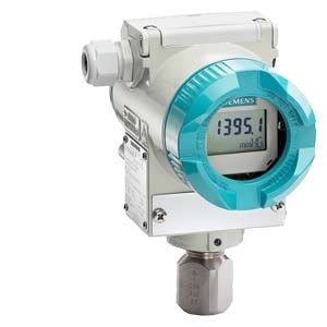
SITRANS P310 for gauge pressure
- Заказные данные (1)
- Аксессуары (28)
- Информационные материалы
Чертеж
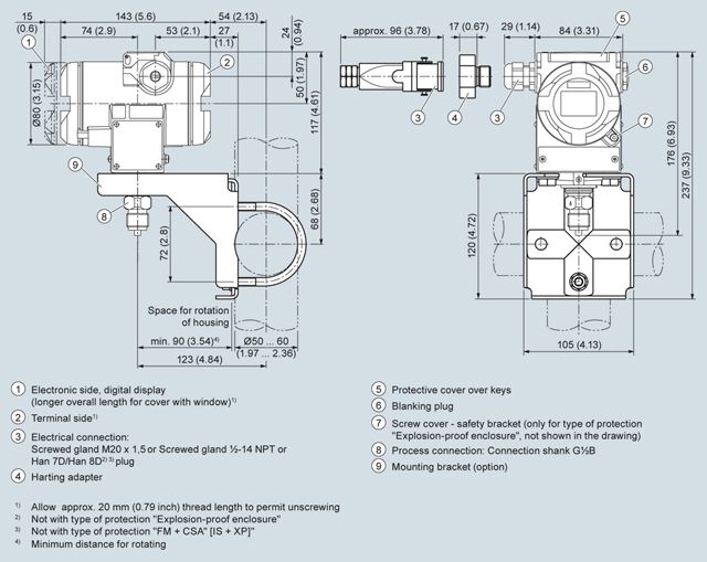
SITRANS P310 pressure transmitter for gauge pressure, dimensions in mm (inches)
Технические данные
SITRANS P310 for gauge pressure
Input
Measured variable
Gauge pressure
Span (fully adjustable) or nominal measuring range, max. operating pressure (in accordance with 2014/68/EU Pressure Equipment Directive) and max. test pressure (pursuant to DIN 16086)
Span
Max. perm. operating pressure MAWP (PS)
Max. permissible test pressure
0.01 ... 1 bar
1 ... 100 kPa
0.15 ... 14.5 psi4 bar
400 kPa
58 psi6 bar
600 kPa
87 psi0.04 ... 4 bar
4 ... 400 kPa
0.58 ... 58 psi7 bar
0.7 Mpa
102 psi10 bar
1 MPa
145 psi0.16 ... 16 bar
16 ... 1600 kPa
2.3 ... 232 psi21 bar
2.1 MPa
305 psi32 bar
3.2 MPa
464 psi0.63 ... 63 bar
63 ... 6300 kPa
9.1 ... 914 psi67 bar
6.7 MPa
972 psi100 bar
10 MPa
1450 psi1.6 ... 160 bar
0.16 ... 16 MPa
23 ... 2321 psi167 bar
16.7 MPa
2422 psi250 bar
25 MPa
3626 psi4 ... 400 bar
0.4 ... 40 MPa
58 ... 5802 psi400 bar
40 MPa
5802 psi600 bar
60 MPa
8702 psi7 ... 700 bar
0.7 ... 70 MPa
102 ... 10153 psi800 bar
80 MPa
11603 psi800 bar
80 MPa
11603 psiLow measuring limit
- Measuring cell with silicone oil filling
30 mbar a/3 kPa a/0.44 psia
Upper measuring limit
100 % of max. span
Start of scale
Between the measuring limits (continuously adjustable)
Output
Output signal
4 ... 20 mA
- Lower limit (fully adjustable)
3.55 mA, factory preset to 3.84 mA
- Upper limit (fully adjustable)
23 mA, factory preset to 20.5 mA or optionally set to 22.0 mA
Load
- Without HART
RB ≤ (UH - 10.5 V)/0.023 A in Ω,
UH: Power supply in V- With HART
RB = 230 ... 500 Ω (SIMATIC PDM) or
RB = 230 ... 1100 Ω (HART Communicator)Protection against polarity reversal
Protected against short-circuit and polarity reversal. Each connection against the other with max. supply voltage.
Electrical damping (step width 0.1 s)
Set to 2 s (0 ... 100 s)
Measuring accuracy
According to IEC 60770-1
Reference conditions
- Rising characteristic curve
- Start of scale 0 bar
- Seal diaphragm stainless steel
- Silicone oil filling
- Room temperature 25 °C (77 °F)
Measuring span ratio r (spread, Turn-Down)
r = maximum measuring span/set measuring span
Error in measurement at limit setting including hysteresis and reproducibility
- Linear characteristic
- 1 bar/100 kPa/3.6 psi
4 bar/400 kPa/58 psi
16 bar/1.6 MPa/232 psi
63 bar/6.3 MPa/914 psi
160 bar/16 MPa/2321 psi
r ≤ 5
5 < r ≤ 100≤ 0.075 %
≤ (0.005 · r + 0.07) %- 400 bar/40 MPa/5802 psi
700 bar/70 MPa/10152 psi
r ≤ 3
3 < r ≤ 100≤ 0.075 %
≤ (0.005 · r + 0.07) %Influence of ambient temperature (in percent per 28 °C (50 °F))
- At -40 … +85 °C (-40 … 185 °F)
≤ (0.15 · r + 0.25) %
Long-term stability (temperature change ±30 °C (±54 °F))
≤ (0.25 · r) % in 5 years
Influence of mounting position
≤ 0.05 mbar/0.005 kPa/0.000725 psi per 10° incline (zero point correction is possible with position error compensation)
Effect of auxiliary power (in percent per voltage change)
0.005 % per 1 V
Rated conditions
Degree of protection according to IEC 60529
IP66 (optional IP66/IP68), NEMA 4X
Temperature of medium
- Measuring cell with silicone oil filling
-40 ... +100 °C (-40 ... +212 °F)
- In conjunction with dust explosion protection
-20 ... +60 °C (-4 ... +140 °F)
Ambient conditions
- Ambient temperature
- Transmitters
-40 ... +85 °C (-40 ... +185 °F)
- Display readable
-30 ... +85 °C (-22 ... +185 °F)
- Storage temperature
-50 ... +85 °C (-58 ... +185 °F)
- Climatic class
- Condensation
Relative humidity 0 ... 100 %
Condensation permissible, suitable for use in the tropics- Electromagnetic compatibility
- Emitted interference and interference immunity
According to IEC 61326 and NAMUR NE 21
Design
Weight (without options)
Die-cast aluminum: ≈ 2.0 kg (≈ 4.4 lb)
Stainless steel precision casting: ≈ 4.6 kg (≈ 10.1 lb)Enclosure material
Low-copper die-cast aluminum, GD-AlSi 12 or stainless steel precision casting, mat. no. 1.4408
Wetted parts materials
- Connection shank
Stainless steel, mat. no. 1.4404/316L or Hastelloy C4, mat. no. 2.4602
- Seal diaphragm
Stainless steel, mat. no. 1.4404/316L or Hastelloy C276, mat. no. 2.4819
Measuring cell filling
Silicone oil or inert fill fluid (for oxygen measurement, maximum pressure 100 bar (1450 psi) at 60 °C (140 °F))
Process connection
G½B connection shank according to DIN EN 837-1; female thread ½-14 NPT or external thread M20x1.5
Material of mounting bracket
Steel
Sheet-steel, mat. no. 1.0330, chrome-plated
Stainless steel
Sheet stainless steel, mat. no. 1.4301 (SS 304)
Power supply UH
Terminal voltage on transmitter
10.5 ... 45 V DC
10.5 ... 30 V DC in intrinsically-safe modeCertificates and approvals
HART
Classification according to pressure equipment directive (PED 2014/68/EU)
For gases of fluid group 1 and liquids of fluid group 1; complies with requirements of article 4, paragraph 3 (sound engineering practice)
Explosion protection
- Intrinsic safety "i"
PTB 13 ATEX 2007 X
- Marking
Ex II 1/2 G Ex ia/ib IIC T4/T5/T6 Ga/Gb
- Permissible ambient temperature
-40 ... +85 °C (-40 ... +185 °F) temperature class T4;
-40 ... +70 °C (-40 ... +158 °F) temperature class T5;
-40 ... +60 °C (-40 ... +140 °F) temperature class T6- Wiring
To certified intrinsically-safe circuits with peak values:
Ui = 30 V, Ii = 100 mA, Pi = 750 mW; Ri = 300 Ω- Effective internal inductance/capacitance
Li = 0.4 mH, Ci = 6 nF
- Flameproof enclosure "d"
PTB 99 ATEX 1160
- Marking
Ex II 1/2 G Ex d IIC T4/T6 Gb
- Permissible ambient temperature
-40 ... +85 °C (-40 ... +185 °F) temperature class T4;
-40 ... +60 °C (-40 ... +140 °F) temperature class T6- Wiring
To circuits with operating values: UH = 10.5 ... 45 V DC
- Dust explosion protection for zone 20
PTB 01 ATEX 2055
- Marking
Ex II 1 D Ex ta IIIC T120 °C Da
Ex II 1/2 D Ex ta/tb IIIC T120 °C Da/Db- Perm. Ambient temperature
-40 ... +85 °C (-40 ... +185 °F)
- Max. surface temperature
120 °C (248 °F)
- Wiring
To certified intrinsically-safe circuits with peak values:
Ui = 30 V, Ii = 100 mA, Pi = 750 mW, Ri = 300 Ω- Effective internal inductance/capacitance
Li = 0.4 mH, Ci = 6 nF
- Dust explosion protection for zone 21/22
PTB 01 ATEX 2055
- Marking
Ex II 2 D Ex tb IIIC T120 °C Db
- Wiring
To circuits with operating values: UH = 10.5 ... 45 V DC; Pmax = 1.2 W
- Type of protection "n" (zone 2)
PTB 13 ATEX 2007 X
- Marking
Ex II 2/3 G Ex nA IIC T4/T5/T6 Gc
Ex II 2/3 G Ex ic IIC T4/T5/T6 Gc- Connection (Ex nA)
Um = 45 V
- Connection (Ex ic)
To circuits with operating values:
Ui = 45 V- Effective internal inductance/capacitance
Li = 0.4 mH, Ci = 6 nF
- Explosion protection acc. to FM
Certificate of Compliance 3008490
- Marking (XP/DIP) or (IS); (NI)
CL I, DIV 1, GP ABCD T4...T6; CL II, DIV 1, GP EFG; CL III; CL I, ZN 0/1 AEx ia IIC T4...T6; CL I, DIV 2, GP ABCD T4...T6; CL II, DIV 2, GP FG; CL III
- Explosion protection to CSA
Certificate of Compliance 1153651
- Marking (XP/DIP) or (IS)
CL I, DIV 1, GP ABCD T4...T6; CL II, DIV 1, GP EFG; CL III; Ex ia IIC T4...T6; CL I, DIV 2, GP ABCD T4...T6; CL II, DIV 2, GP FG; CL III
Communication
HART
230 ... 1100 Ω
Protocol
HART Version 5.x
Software for computer
SIMATIC PDM