
- Каталог оборудования Siemens
- Каталог продуктов Siemens Industry
- Приводная техника
- Техника автоматизации
- Системы автоматизации
- Системы визуализации SIMATIC HMI
- Системы идентификации
- Промышленные коммуникации SIMATIC NET
- Промышленные аппараты управления SIRIUS
- Промышленные информационные технологии
- Управление на базе РС
- Системы управления процессом
- Контрольно-измерительные приборы
- Анализаторы процесса
- Блоки питания SITOP
- Блоки питания серии SITOP lite
- SITOP compact
- Блоки питания серии LOGO!Power
- SITOP lite
- Блоки питания серии SITOP smart
- Модульные блоки питания SITOP
- SITOP modular, PSU8600 power supply system
- SITOP в исполнении SIMATIC
- Специальное исполнение и назначение
- Дополнительные компоненты
- Блоки бесперебойного питания DC-UPS
- Аксессуары
- Блоки питания заказного исполнения
- Семейство SIPLUS
- SIPLUS DC-UPS, бесперебойные источники питания
- Блоки питания для AS-интерфейса
- Техническая информация и проектирование
- SITOP power для AS-Interface
- Продукты для специальных требований
- Energy
- Автоматизация и безопасность зданий
- Низковольтная коммутационная техника
- Технология безопасности
- Системные решения и продукты для отраслей
- Сервис
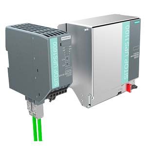
SITOP UPS1600 DC UPS modules
- Заказные данные (9)
- Информационные материалы
Информационные материалы
By combining one DC UPS module SITOP UPS1600 with at least one UPS1100 battery module and a SITOP power supply unit, longer power failures can be bridged without any interruption. The intelligent battery management automatically detects the UPS1100 energy storage unit, ensures optimized temperature-specific charging and continuous monitoring. The compact DC UPS modules have overload capability, for example, to supply the inrush current of industrial PCs. In stand-alone mode, they support starting from the battery.
The DC UPS communicates openly over a USB or Ethernet/PROFINET port. It is easily integrated into the PC or PLC environment over the two Ethernet/PROFINET ports. Total integration in TIA provides user-friendly engineering in the TIA Portal and is supported with ready-to-use function blocks for S7 user programs and WinCC faceplates for fast visualization.
SITOP UPS Manager supports easy monitoring and configuration in PC systems, e.g. shutdown of several PCs in accordance with the master-slave principle. The integrated web server supports remote monitoring of the DC UPS.
Область применения
The battery modules that can be connected in parallel bridge power failures for a few hours. This supports the continued operation of processes or parts of them. The function "Starting from the battery" means that the UPS1600 can also be used in stand-alone mode without connection to the supply.
Depending on the communication requirements between the DC UPS and the automation components to be protected against power failure, the version of UPS1600 can be selected accordingly.
Buffering of simple automation applications
In simple applications with mini PLCs (e.g. obstruction lights, stand-alone hydro-electric plants), 24 V buffering is performed by the UPS1600 without a communications interface. The status messages are transferred to the PLC via the digital outputs (isolated).

Buffering of applications with automation computer
The UPS1600 with a USB interface is used to buffer automation solutions that are controlled by an industrial PC. All operating and configuring data is communicated over the PC interface.

Communication over Ethernet/PROFINET offers the most comprehensive possibilities for diagnostics and system integration. The UPS1600 can be directly integrated into the LAN infrastructure over its two ports.
Buffering of applications with networked (Industrial Ethernet) automation computers
The UPS1600 with Industrial Ethernet interface protects complex PC-based applications from power failure. Configuration and monitoring is performed using the PC software SITOP UPS Manager. It also supports defined shutdown of several PCs in accordance with the master-slave principle.

Buffering of applications with networked (PROFINET) automation components
For buffering sensitive plant components (e.g. a pumping station with telecontrol) or complete controller solutions (e.g. machine tools) that are integrated into a networked automation solution, the UPS1600 with PROFINET is the perfect choice. Total integration in TIA offers unique advantages for engineering and operation (e.g. diagnostics or visualization). For example, in buffer mode, several controllers can be brought to a defined independently of each other.

Дизайн
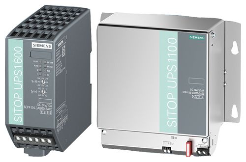
- Compact DC UPS modules UPS1600 24 V/10 A, 20A and 40 A with digital inputs and outputs, optionally with USB interface or two Ethernet/PROFINET ports
- UPS1100 battery modules 1.2 Ah, 3.2 Ah, 7 Ah and 12 Ah with lead rechargeable batteries, UPS1100 2.5 Ah battery module with pure-lead rechargeable batteries and UPS1100 5 Ah battery module with lithium-ion technology.
Функции
SITOP UPS1600 web server
The SITOP UPS1600 with Ethernet/PROFINET has an integrated web server that supports remote monitoring and control of the uninterruptible power supply. Using HTTPS ensures encrypted and safe data transmission.
Remote monitoring and control of:
- Hardware configuration data
- Remote monitoring
- Operating data of the UPS1600 basic unit and the connected UPS1100 battery module
- Alarm messages
Remote access via:
- Firefox 34 or higher, or Internet Explorer 10, 11 (IE 8 with charging of SVG player)
- IP address
- Password
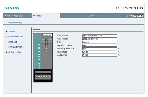
The password-protected web server supports viewing of the configuring and operating data.
SITOP UPS1600 software
Software tools support convenient integration of the SITOP UPS1600 in both PC-based and PLC-based systems. They make configuring and visualizing the DC UPS easier and the user benefits from the high performance of the SITOP UPS1600.
Software for open, PC-based automation systems
SITOP UPS Manager
Configuration and monitoring is performed easily using the free PC software SITOP UPS Manager. It enables the reactions of the PC to the operating states of the DC UPS to be freely selected and offers comprehensive diagnostic options:
- Configuration
- Connection via USB or Ethernet
- All the relevant parameters can be configured in UPS Manager and transferred to the UPS1600
- Configuration of "non-coded" rechargeable batteries is possible
- The reactions of the PC to the operating states of the UPS can be freely selected, e.g. termination of software applications
- Support for reliable downloading of several PCs according to the master-slave principle
- The configurations can be saved locally
- Integrated OPC UA server
- Updating of the UPS1600 firmware is possible
- Assignment of IP addresses and device names of the UPS1600
- Can run under Windows XP, Windows 7 (32-bit and 64-bit) operating systems
- Monitoring
- Readout and display of alarms, statuses and operating variables of the UPS1600 and the connected energy storage unit
- Tracing of history in trend diagrams

Monitor window for battery status in SITOP UPS Manager

Trend diagram for load current in SITOP UPS Manager
Software for TIA-based automation systems
For convenient integration of the DC UPS in the TIA environment, different software modules are available.
Engineering is simple via the TIA Portal. The data for UPS1600 is stored in the hardware catalog version V14 and higher. Special function blocks for SIMATIC S7-300, S7-400, S7-1200 and S7-1500 also support integration in the STEP 7 user program.
The comprehensive diagnostics data of the UPS1600 power supply can be visualized using prepared UPS faceplates for WinCC.
TIA Portal
- Convenient and fail-safe integration of SITOP UPS1600 in the PROFINET network by means of drag-and-drop
- Convenient configuration of SITOP UPS1600 basic units with Ethernet/PROFINET and the UPS1100 battery module simply by selecting from the TIA Portal hardware catalog
- Free download of HSP (Hardware Support Package) for TIA Portal version V12 SP1 or higher available at
http://support.automation.siemens.com/WW/view/en/75854606 - Free GSD file (Generic Station Description) for STEP 7 V 5.5
http://support.automation.siemens.com/WW/view/en/75854605
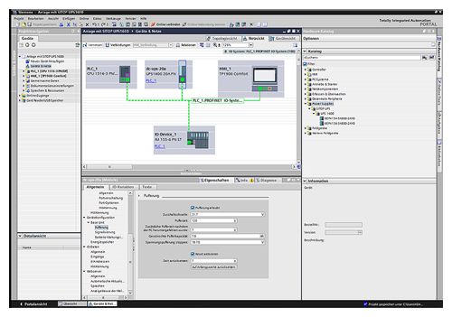
Establishing the PROFINET connection between the SITOP UPS1600 and the controller is easy and fail-safe in the TIA Portal
STEP 7 function blocks
Function blocks are available for STEP 7 user programs on SIMATIC S7-300/400/1200/1500. They allow further processing of the DC UPS operating data.
- Function blocks for STEP 7 V5.5
- Function blocks from STEP 7 V12 and higher
Free download:
http://support.automation.siemens.com/WW/view/en/75854608Faceplates for WinCC
Ready-to-use faceplates save programming time for visualization of the uninterruptible power supply. The faceplates show all relevant statuses and values of the DC UPS. They are available for the following systems:
- Faceplates for WinCC V7.2
- Faceplates for WinCC flexible 2008 SP3
- Faceplates for WinCC Comfort/Advanced/Professional V12
Free download:
http://support.automation.siemens.com/WW/view/en/75854608
The pre-compiled WinCC faceplates show all the relevant UPS data in a clearly comprehensible display. An icon with color coding for the operating state is also available
Software for SIMATIC PCS 7 process control system
The SITOP library is available with blocks and faceplates for direct integration into SIMATIC PCS 7. The SW blocks in the SIMATIC S7 supply the faceplate on the user interface of the process control system with operating and diagnostics data, generate messages and ensure connection to the maintenance system of PCS 7. This means that PCS 7 users automatically receive information about operating state conditions, maintenance requirements (e.g. battery replacement) and disturbances (e.g. power failures). This ensures constant transparency of the 24V supply in the control system. The SITOP library supports the following SIMATIC PCS 7 versions:
- SIMATIC PCS 7 V8.0 with SP2
- SIMATIC PCS 7 V8.1
- SIMATIC PCS7 V8.1 with SP1
- SIMATIC PCS7 V8.2 available soon
Free download at:
https://support.industry.siemens.com/cs/ww/en/view/109476154Особенности
- 24 V buffering for a few hours for the purpose of continuing processes
- Open communication over USB or two Ethernet/PROFINET ports
- High-performance DC UPS modules in space-saving, slim design
- High overload capability for mains and buffering operation
- Starting from the battery module supports stand-alone mode, e.g. for starting generators
- Easy configuration thanks to automatic detection of battery modules
- High reliability and availability due to monitoring of the operational readiness, battery feeder, aging and charging status
- Battery protecting charging due to temperature-specific charging characteristic
- Defined shutdown of several PCs or controllers on one UPS (versions with Ethernet/PROFINET)
- Remote monitoring via integrated web server
(versions with Ethernet/PROFINET) - Time-saving engineering in PC-based systems via SITOP UPS Manager (versions with USB or Ethernet/PROFINET)
- SITOP UPS Manager with OPC UA server facilitates flexible, multi-vendor communication with other systems
- Full integration in TIA saves time and costs during the planning stage and in operation (versions with Ethernet/PROFINET)
- User-friendly engineering in the TIA Portal
- SIMATIC S7 function blocks for easy integration in STEP 7 user programs
- Fast integration in operator control and monitoring with WinCC faceplates
- Direct integration in SIMATIC PCS 7 via SITOP library
Технические данные
Order number
6EP4134-3AB00-0AY0
6EP4134-3AB00-1AY0
6EP4134-3AB00-2AY06EP4136-3AB00-0AY0
6EP4136-3AB00-1AY0
6EP4136-3AB00-2AY06EP4137-3AB00-0AY0
6EP4137-3AB00-1AY0
6EP4137-3AB00-2AY0product brandname
SITOP UPS1600
SITOP UPS1600
SITOP UPS1600
Type of current supply
DC UPS 24 V/10 A
DC UPS 24 V/20 A
DC UPS 24 V/40 A
Input
Supply voltage at DC Rated value
24 V
24 V
24 V
Voltage curve at input
DC
DC
DC
input voltage range
22 ... 29 V DC
22 ... 29 V DC
22 ... 29 V DC
Adjustable response value voltage for buffer connection preset
22.5 V
22.5 V
22.5 V
Adjustable response value voltage for buffer connection
21 ... 25 V; Adjustable: 21 V, 21.5 V, 22 V, 22.5 V, 23 V, 24 V, 25 V DC or via software
21 ... 25 V; Adjustable: 21 V, 21.5 V, 22 V, 22.5 V, 23 V, 24 V, 25 V DC or via software
21 ... 25 V; Adjustable: 21 V, 21.5 V, 22 V, 22.5 V, 23 V, 24 V, 25 V DC or via software
Input current at rated input voltage 24 V Rated value
14 A; for max. charging current (3 A)
25 A; for max. charging current (4 A)
46 A; for max. charging current (5 A)
Mains buffering
Type of energy storage
with batteries
with batteries
with batteries
Design of the mains power cut bridging-connection
Adjustable range using rotary coding switch: 0.5 min, 1 min, 2 min, 5 min, 10 min, 20 min, max. buffering time or via software
Adjustable range using rotary coding switch: 0.5 min, 1 min, 2 min, 5 min, 10 min, 20 min, max. buffering time or via software
Adjustable range using rotary coding switch: 0.5 min, 1 min, 2 min, 5 min, 10 min, 20 min, max. buffering time or via software
Charging current
● 1
0.1 A
0.1 A
0.1 A
● 2
3 A
4 A
5 A
adjustable charging current maximum Note
Automatically depending on battery module
Automatically depending on battery module
Automatically depending on battery module
Output
Output voltage
● in normal operation at DC Rated value
24 V
24 V
24 V
● in buffering mode at DC Rated value
24 V
24 V
24 V
Formula for output voltage
Vin - approx. 0.01 x I
Vin - approx. 0.01 x I
Vin - approx. 0.01 x I
ON-delay time typical
60 s
60 s
60 s
Voltage increase time of the output voltage typical
60 ms
60 ms
60 ms
Output voltage in buffering mode at DC
19 ... 28.5 V
19 ... 28.5 V
19 ... 28.5 V
Output current
● Rated value
10 A
20 A
40 A
● in normal operation
0 ... 30 A
0 ... 60 A
0 ... 120 A
● in buffering mode
0 ... 30 A
0 ... 60 A
0 ... 120 A
Peak current
30 A
60 A
120 A
Property of the output Short-circuit proof
Yes
Yes
Yes
Design of short-circuit protection
Limitation to 3 x I rated for 30 ms/min; through-conductivity for 1.5 x I rated for 5 sec/min
Limitation to 3 x I rated for 30 ms/min; through-conductivity for 1.5 x I rated for 5 sec/min
Limitation to 3 x I rated for 30 ms/min; through-conductivity for 1.5 x I rated for 5 sec/min
Supplied active power typical
240 W
480 W
960 W
Efficiency
Efficiency in percent
● at rated output current at rated output current typical
97.7 %
98.2 %
98.8 %
● in case of accumulator operation typical
97.7 %
98.2 %
98.8 %
Power loss [W]
● at rated output current at rated output current typical
5.6 W
8.6 W
12 W
● in case of accumulator operation typical
5.6 W
8.6 W
12 W
Protection and monitoring
Product function
● reverse polarity protection against energy storage unit polarity reversal
Yes
Yes
Yes
● reverse polarity protection against input voltage polarity reversal
Yes
Yes
Yes
Signaling
Display version
● for normal operation
Normal operation: LED green (OK), floating changeover contact "Bat/OK" to setting "OK" ("OK" means: Voltage of the supplying power supply unit is greater than cut-in threshold set at the DC UPS module); Lack of buffer standby: LED red (alarm), floating changeover contact "Alarm/Bat" to setting "Alarm"; Battery replacement required: LED red (alarm) flashing with approx. 0.25 Hz, floating changeover contact "Alarm/Bat" switching with approx. 0.25 Hz; Energy storage > 85%: LED green (Bat > 85%), floating NO contact "Bat > 85" closed; Permissible contact current capacity: DC 60 V/1 A or AC 30 V /1 A
Normal operation: LED green (OK), floating changeover contact "Bat/OK" to setting "OK" ("OK" means: Voltage of the supplying power supply unit is greater than cut-in threshold set at the DC UPS module); Lack of buffer standby: LED red (alarm), floating changeover contact "Alarm/Bat" to setting "Alarm"; Battery replacement required: LED red (alarm) flashing with approx. 0.25 Hz, floating changeover contact "Alarm/Bat" switching with approx. 0.25 Hz; Energy storage > 85%: LED green (Bat > 85%), floating NO contact "Bat > 85" closed; Permissible contact current capacity: DC 60 V/1 A or AC 30 V /1 A
Normal operation: LED green (OK), floating changeover contact "Bat/OK" to setting "OK" ("OK" means: Voltage of the supplying power supply unit is greater than cut-in threshold set at the DC UPS module); Lack of buffer standby: LED red (alarm), floating changeover contact "Alarm/Bat" to setting "Alarm"; Battery replacement required: LED red (alarm) flashing with approx. 0.25 Hz, floating changeover contact "Alarm/Bat" switching with approx. 0.25 Hz; Energy storage > 85%: LED green (Bat > 85%), floating NO contact "Bat > 85" closed; Permissible contact current capacity: DC 60 V/1 A or AC 30 V /1 A
● in buffering mode
Buffered mode: LED yellow (Bat), floating changeover contact "OK/Bat" to setting "Bat"; Prewarning battery voltage < 20.4 VDC: LED red (alarm), floating changeover contact "Alarm/Bat" to setting "Alarm"; Energy storage > 85%: LED green (Bat > 85%), floating NO contact "Bat > 85" closed
Buffered mode: LED yellow (Bat), floating changeover contact "OK/Bat" to setting "Bat"; Prewarning battery voltage < 20.4 VDC: LED red (alarm), floating changeover contact "Alarm/Bat" to setting "Alarm"; Energy storage > 85%: LED green (Bat > 85%), floating NO contact "Bat > 85" closed
Buffered mode: LED yellow (Bat), floating changeover contact "OK/Bat" to setting "Bat"; Prewarning battery voltage < 20.4 VDC: LED red (alarm), floating changeover contact "Alarm/Bat" to setting "Alarm"; Energy storage > 85%: LED green (Bat > 85%), floating NO contact "Bat > 85" closed
Interface
Product component PC interface
No
No
Yes
Design of the interface
without
without
without
Safety
Galvanic isolation between entrance and outlet
No
No
No
Operating resource protection class
Class III
Class III
Class III
Certificate of suitability
● CE marking
Yes
Yes
Yes
● as approval for USA
cULus-Listed (UL 508, CSA C22.2 No. 107.1), File E197259
cULus-Listed (UL 508, CSA C22.2 No. 107.1), File E197259
cULus-Listed (UL 508, CSA C22.2 No. 107.1), File E197259
● relating to ATEX
IECEx Ex nA nC IIC T4 Gc; cCSAus (CSA C22.2 No. 213-M1987, ANSI/ISA-12.12.01-2013) Class I, Div. 2, Group ABCD, T4
IECEx Ex nA nC IIC T4 Gc; cCSAus (CSA C22.2 No. 213-M1987, ANSI/ISA-12.12.01-2013) Class I, Div. 2, Group ABCD, T4
IECEx Ex nA nC IIC T4 Gc; cCSAus (CSA C22.2 No. 213-M1987, ANSI/ISA-12.12.01-2013) Class I, Div. 2, Group ABCD, T4
● C-Tick
Yes
Yes
Yes
Type of certification CB-certificate
Yes
Yes
Yes
Shipbuilding approval
GL, ABS
GL, ABS
GL, ABS
Protection class IP
IP20
IP20
IP20
EMC
Standard
● for emitted interference
EN 55022 Class B
EN 55022 Class B
EN 55022 Class B
● for interference immunity
EN 61000-6-2
EN 61000-6-2
EN 61000-6-2
Operating data
Ambient temperature
● during operation
-25 ... +70 °C; with natural convection
-25 ... +70 °C; with natural convection
-25 ... +70 °C; with natural convection
● during transport
-40 ... +85 °C
-40 ... +85 °C
-40 ... +85 °C
● during storage
-40 ... +85 °C
-40 ... +85 °C
-40 ... +85 °C
Environmental category acc. to IEC 60721
Climate class 3K3, no condensation
Climate class 3K3, no condensation
Climate class 3K3, no condensation
Mechanics
Type of electrical connection
screw-type terminals
screw-type terminals
screw-type terminals
● at input
24 V DC: 2 screw terminals for 0.2 ... 6 mm²/24 ... 13 AWG
24 V DC: 2 screw terminals for 0.2 ... 6 mm²/24 ... 13 AWG
24 V DC: 2 screw terminals for 0.5 ... 16 mm²/20 ... 6 AWG
● at output
24 V DC: 2 screw terminals for 0.2 ... 6 mm²/24 ... 13 AWG
24 V DC: 2 screw terminals for 0.2 ... 6 mm²/24 ... 13 AWG
24 V DC: 2 screw terminals for 0.5 ... 16 mm²/20 ... 6 AWG
● for battery module
24 V DC: 2 screw terminals for 0.2 ... 6 mm²/24 ... 13 AWG
24 V DC: 2 screw terminals for 0.2 ... 6 mm²/24 ... 13 AWG
24 V DC: 2 screw terminals for 0.5 ... 16 mm²/20 ... 6 AWG
● for control circuit and status message
14 screw terminals for 0.2 ... 1.5 mm²/24 ... 16 AWG
14 screw terminals for 0.2 ... 1.5 mm²/24 ... 16 AWG
14 screw terminals for 0.2 ... 1.5 mm²/24 ... 16 AWG
Width of the enclosure
50 mm
50 mm
70 mm
Height of the enclosure
125 mm
125 mm
125 mm
Depth of the enclosure
125 mm
125 mm
150 mm
Required spacing
● top
50 mm
50 mm
50 mm
● bottom
50 mm
50 mm
50 mm
● left
0 mm
0 mm
0 mm
● right
0 mm
0 mm
0 mm
Net weight
0.38 kg
0.39 kg
0.65 kg
Product feature of the enclosure housing for side-by-side mounting
Yes
Yes
Yes
Mounting type
Snaps onto DIN rail EN 60715 35x7.5/15
Snaps onto DIN rail EN 60715 35x7.5/15
Snaps onto DIN rail EN 60715 35x7.5/15
Electrical accessories
Battery module
Battery module
Battery module
MTBF at 40 °C
415 574 h
408 654 h
372 738 h
Equipment marking acc. to DIN EN 81346-2
T
T
T
Other information
Specifications at rated input voltage and ambient temperature +25 °C (unless otherwise specified)
Specifications at rated input voltage and ambient temperature +25 °C (unless otherwise specified)
Specifications at rated input voltage and ambient temperature +25 °C (unless otherwise specified)