
- Каталог оборудования Siemens
- Каталог продуктов Siemens Industry
- Приводная техника
- Техника автоматизации
- Системы автоматизации
- Системы визуализации SIMATIC HMI
- Системы идентификации
- Промышленные коммуникации SIMATIC NET
- Промышленные аппараты управления SIRIUS
- Промышленные информационные технологии
- Управление на базе РС
- Системы управления процессом
- Контрольно-измерительные приборы
- Измерительные преобразователи для давления
- Transmitter for rel. pressure, abs. pressure, diff. pressure, flow and level
- Измерительные преобразователи для любых применений во всех отраслях промышленности
- Преобразователь для работы по протоколу WirelessHART
- Преобразователи давления для пищевой, фармацевтической промышленностей и биотехнологий
- Преобразователи давления для бумажной промышленности
- Преобразователи общего назначения
- Измерительные преобразователи для применений с повышенными тебованиями
- Высокоэффективные измерительные преобразователи
- SITRANS P разделители давления (HID: print)
- Фитинги
- Transmitter for rel. pressure, abs. pressure, diff. pressure, flow and level
- Приборы измерения температуры SITRANS T
- Расходомеры
- Уровнемеры
- Позиционеры
- Устройство для защиты и пуска двигателей SIMOCODE-DP
- Сигнализаторы сбоев в промышленном процессе
- Аппаратные ПИД-регуляторы SIPART
- Встраиваемые самописцы и индикаторы
- Технологии взвешивания
- Дополнительные компоненты
- Коммуникации и программное обеспечение
- Directives
- Измерительные преобразователи для давления
- Анализаторы процесса
- Блоки питания SITOP
- Продукты для специальных требований
- Energy
- Автоматизация и безопасность зданий
- Низковольтная коммутационная техника
- Технология безопасности
- Системные решения и продукты для отраслей
- Сервис
SITRANS P300 (gauge pressure and absolute pressure)
- Заказные данные (2)
- Аксессуары (21)
- Информационные материалы
Информационные материалы
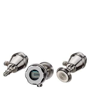
The SITRANS P300 is a digital pressure transmitter for gage and absolute pressure. All conventional thread versions are available as process connections. In addition, various hygiene-based connections and flange connections with front-flush diaphragms meet the requirements of a dead space free process connection.
The output signal is a load-independent direct current from 4 t 20 mA or a PROFIBUS PA signal, which is linearly proportional to the input pressure. Communication is over HART protocol or over PROFIBUS PA interface. Convenient buttons for easy local operation of the basic settings of the pressure transmitter.
The SITRANS P300 has a single-chamber stainless steel casing. The pressure transmitter is approved with "intrinsically safe" type of protection It can be used in zone 1 or zone 0.
Область применения
The pressure transmitter is available in versions for gauge pressure and for absolute pressure. The output signal is always a load-independent direct current from 4 to 20 mA or a PROFIBUS PA signal, which is linearly proportional to the input pressure. The pressure transmitter measures aggressive, non-aggressive and hazardous gases, as well as vapors and liquids.
It can be used for the following measurement types:
- Gauge pressure
- Absolute pressure
With appropriate parameter settings, it can also be used for the following additional measurement types:
- Level
- Volume
- Mass
The "intrinsically-safe" EEx version of the transmitter can be installed in hazardous areas (zone 1). The transmitters are provided with an EC type examination certificate and comply with the respective harmonized European standards of ATEX.
Gauge pressure
This variant measures aggressive, non-aggressive and hazardous gases, vapors and liquids.
The smallest measuring span is 0.01 bar g, the largest 400 bar g (0.15 psi g, the largest 5802 psi g).
Level
With appropriate parameter settings, the gauge pressure variant measures the level of aggressive, non-aggressive and hazardous liquids.
For measuring the level in an open container you require one device; for measuring the level in a closed container, you require two devices and a process control system.
Absolute pressure
This variant measures the absolute pressure of aggressive, non-aggressive and hazardous gases, vapors and liquids.
The smallest measuring span is 0.008 bar a, the largest 30 bar a (0.12 psi a, the largest 435 psi a).
Дизайн
The device comprises:
- Electronics
- Housing
- Measuring cell
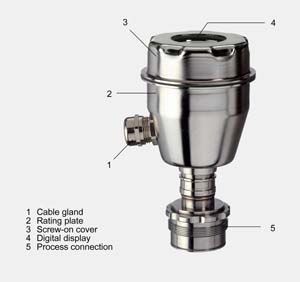
Perspective view of the SITRANS P300
The housing has a screw-on cover (3) and, depending on the version, is with or without an inspection window. The electrical terminal housing, the buttons for operation of the device are located under this cover and, depending on the version, the digital display. The connections for the auxiliary power UH and the shield are in the terminal housing. The cable gland is mounted on the side of the housing. The measuring cell with the process connection (5) is located on the bottom of the housing. The measuring cell with the process connection may differ from the one shown in the diagram, depending on the device version.
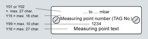
Measuring point label
Функции
Operation of electronics with HART communication
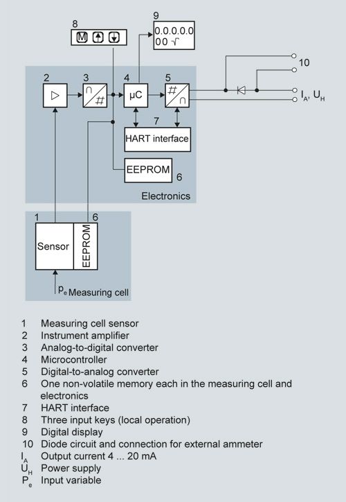
Function diagram of electronics
The input pressure is converted into an electrical signal by the sensor (1). This signal is amplified by the measuring amplifier (2) and digitalized in an analog-to-digital converter (3). The digital signal is analyzed in a microcontroller (4) and corrected according to linearity and thermal characteristics. In a digital-to-analog converter (5) it is then converted into the output current of 4 to 20 mA. A diode circuit provides reverse polarity protection. You can make an uninterrupted current measurement with a low-ohm ammeter at the connection (10). The data specific to the measuring cell, the electronic data and parameter settings are stored in two non-volatile memories (6). The first memory is linked to the measuring cell, the second to the electronics.
The buttons (8) can be used to call up individual functions, so-called modes. If you have a device with a digital display (9), you can use this to track mode settings and other messages. The basic mode settings can be changed with a computer via the HART modem (7).
Operation of electronics with PROFIBUS PA communication
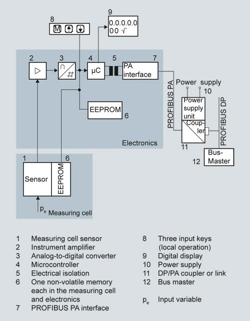
Function diagram of electronics
The input pressure is converted into an electrical signal by the sensor (1). This signal is amplified by the measuring amplifier (2) and digitalized in an analog-to-digital converter (3). The digital signal is analyzed in a microcontroller (4) and corrected according to linearity and thermal characteristics. It is then made available at the PROFIBUS PA over an electrically isolated PROFIBUS PA interface (7). The data specific to the measuring cell, the electronic data and parameter settings are stored in two non-volatile memories (6). The first memory is linked to the measuring cell, the second to the electronics.
The buttons (8) can be used to call up individual functions, so-called modes. If you have a device with a digital display (9), you can use this to track mode settings and other messages. The basic mode settings can be changed with a computer over the bus master (12).
Operation of electronics with FOUNDATION fieldbus communication
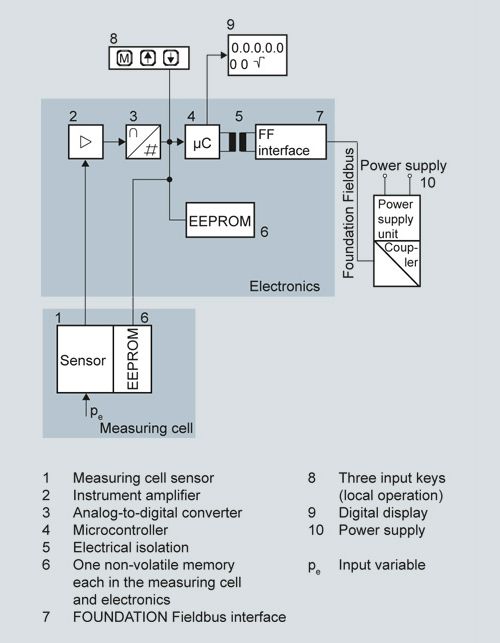
Function diagram of electronics
The bridge output voltage created by the sensor (1, Figure "Function diagram of electronics") is amplified by the measuring amplifier (2) and digitized in the analog-to-digital converter (3). The digital information is evaluated in the microcontroller, its linearity and temperature response corrected, and provided on the FOUNDATION fieldbus through an electrically isolated FOUNDATION fieldbus interface (7).
The data specific to the measuring cell, the electronics data, and the parameter data are stored in the two non-volatile memories (6). The one memory is coupled to the measuring cell, the other to the electronics. As the result of this modular design, the electronics and the measuring cell can be replaced separately from each other.
Using the three input buttons (8) you can parameterize the pressure transmitter directly at the measuring point. The input buttons can also be used to control the view of the results, the error messages and the operating modes on the digital display (9).
The results with status values and diagnostic values are transferred by cyclic data transmission on the FOUNDATION fieldbus. Parameterization data and error messages are transferred by acyclic data transmission. Special software such as National Instruments Configurator is required for this.
Mode of operation of the measuring cells
The process connections available include the following:
- G½
- ½-14 NPT
- Flush-mounted diaphragm:
- Flanges to EN
- Flanges to ASME
- NuG and pharmaceutical connections
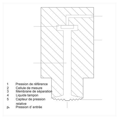
Measuring cell for gauge pressure
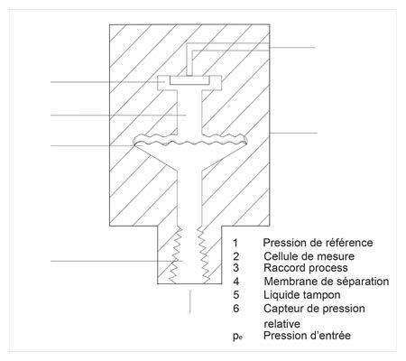
Measuring cell for gauge pressure, function diagram
The input pressure (pe) is transferred to the gauge pressure sensor (6) via the seal diaphragm (4) and the filling liquid (5), displacing its measuring diaphragm. The displacement changes the resistance value of the four piezo resistors in the measuring diaphragm in a bridge circuit. The change in the resistance causes a bridge output voltage proportional to the input pressure.
Transmitters with spans ≤ 63 bar (≤ 926.1 psi) measure the input pressure compared to atmospheric, those with spans ≥ 160 bar (≥ 2352 psi) compared to a vacuum.
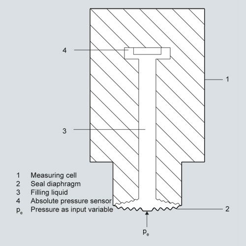
Measuring cell for absolute pressure
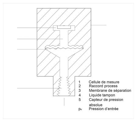
Measuring cell for absolute pressure, function diagram
The input pressure (pe) is transferred to the absolute pressure sensor (5) via the seal diaphragm (3) and the filling liquid (4), displacing its measuring diaphragm. The displacement changes the resistance value of the four piezo resistors in the measuring diaphragm in a bridge circuit. The change in the resistance causes a bridge output voltage proportional to the input pressure.
Measuring cell for gauge pressure, flush-mounted diaphragm
Measuring cell for gauge pressure, flush-mounted diaphragm, function diagram
The input pressure (pe) is transferred to the gauge pressure sensor (6) via the seal diaphragm (4) and the filling liquid (5), displacing its measuring diaphragm. The displacement changes the resistance value of the four piezo resistors in the measuring diaphragm in a bridge circuit. The change in the resistance causes a bridge output voltage proportional to the input pressure.
Transmitters with spans ≤ 63 bar (≤ 926.1 psi) measure the input pressure compared to atmospheric, those with spans ≥ 160 bar (≥ 2352 psi) compared to a vacuum.
Measuring cell for absolute pressure, flush-mounted diaphragm
Measuring cell for absolute pressure, flush-mounted diaphragm, function diagram
The input pressure (pe) is transferred to the absolute pressure sensor (5) via the seal diaphragm (3) and the filling liquid (4), displacing its measuring diaphragm. The displacement changes the resistance value of the four piezo resistors in the measuring diaphragm in a bridge circuit. The change in the resistance causes a bridge output voltage proportional to the input pressure.
Parameterization of SITRANS P300
Depending on the version, there are a range of options for parameterizing the pressure transmitter and for setting or scanning the parameters.
Parameterization using the input buttons (local operation)
With the input buttons you can easily set the most important parameters without any additional equipment.
Parameterization using HART communication
Parameterization using HART communication is performed with a HART communicator or a PC.
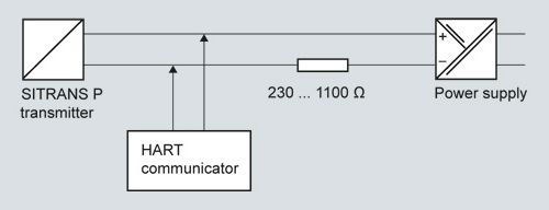
Communication between a HART communicator and a pressure transmitter
When parameterizing with the HART communicator, the connection is made directly to the 2-wire cable.
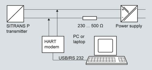
HART communication between a PC communicator and a pressure transmitter
When parameterizing with a PC, the connection is made through a HART modem.
The signals needed for communication in conformity with the HART 5.x or 6.x protocols are superimposed on the output current using the Frequency Shift Keying (FSK) method.
Adjustable parameters on SITRANS P300 with HART communication
Parameters
Input buttons
HART communication
Start of scale
x
x
Full-scale value
x
x
Electrical damping
x
x
Start-of-scale value without application of a pressure ("Blind setting")
x
x
Full-scale value without application of a pressure ("Blind setting")
x
x
Zero adjustment
x
x
current transmitter
x
x
Fault current
x
x
Disabling of buttons, write protection
x
x 1)
Type of dimension and actual dimension
x
x
Input of characteristic
x
Freely-programmable LCD
x
Diagnostic functions
x
1) Cancel apart from write protection
Diagnostic functions for SITRANS P300 with HART communication
- Zero correction display
- Event counter
- Limit transmitter
- Saturation alarm
- Slave pointer
- Simulation functions
- Maintenance timer
Available physical units of display for SITRANS P300 with HART communication
Table style: Technical specifications 2
Physical variable
Physical dimensions
Pressure (setting can also be made in the factory)
Pa, MPa, kPa, bar, mbar, torr, atm, psi, g/cm2, kg/cm2, inH2O, inH2O (4 °C), mmH2O, ftH2O (20 °C), inHg, mmHg
Level (height data)
m, cm, mm, ft, in
Volume
m3, dm3, hl, yd3, ft3, in3, US gallon, lmp. gallon, bushel, barrel, barrel liquid
Mass
g, kg, t, lb, Ston, Lton, oz
Temperature
K, °C, °F, °R
Miscellaneous
%, mA
Parameterization through PROFIBUS PA interface
Fully digital communication through PROFIBUS PA, profile 3.0, is particularly user-friendly. The P300 PA is connected to a process control system, e.g. SIMATIC PSC 7, over PROFIBUS. Communication is possible even in a potentially explosive environment.
For parameterization through PROFIBUS you need suitable software, e.g. SIMATIC PDM (Process Device Manager).
Parameterization through FOUNDATION fieldbus interface
Fully digital communication through FOUNDATION fieldbus is particularly user-friendly. Through the FOUNDATION fieldbus the P300 is connected to a process control system. Communication is possible even in a potentially explosive environment.
For parameterization through the FOUNDATION fieldbus you need suitable software, e.g. National Instruments Configurator.
Adjustable parameters for SITRANS P300 PA and FF
Adjustable parameters
Input buttons
PROFIBUS PA and FOUNDATION fieldbus interface
Electrical damping
x
x
Zero adjustment (correction of position)
x
x
Buttons and/or function disabling
x
x
Source of measured-value display
x
x
Physical dimension of display
x
x
Position of decimal point
x
x
Bus address
x
x
Adjustment of characteristic
x
x
Input of characteristic
x
Freely-programmable LCD
x
Diagnostic functions
x
Diagnostic functions for SITRANS P300 PA and FF
- Event counter
- Slave pointer
- Maintenance timer
- Simulation functions
- Display of zero correction
- Limit transmitter
- Saturation alarm
Physical dimensions available for the display
Physical variable
Physical dimensions
Pressure (setting can also be made in the factory)
MPa, kPa, Pa, bar, mbar, torr, atm, psi, g/cm2, kg/cm2, mmH2O, mmH2O (4 °C), inH2O, inH20 (4 °C), ftH2O (20 °C), mmHg, inHg
Level (height data)
m, cm, mm, ft, in, yd
Volume
m3, dm3, hl, yd3, ft3, in3, US gallon, lmp. gallon, bushel, barrel, barrel liquid
volume flow
m3/s, m3/min, m3/h, m3/d, l/s, l/min, l/h, l/ d, Ml/d, ft3/s, ft3/min, ft3/h, ft3/d, US gallon/s, US gallon/min, US gallon/h, US gallon/d, bbl/s, bbl/min, bbl/h, bbl/d
Mass flow
g/s, g/min, g/h, g/d, kg/s, kg/min, kg/h, kg/d, t/s, t/min, t/h, /t/d, lb/s, lb/min, lb/h, lb/d, STon/s, STon/min, STon/h, STon/d, LTon/s, LTon/min, LTon/h, LTon/d
Total mass flow
t, kg, g, lb, oz, LTon, STon
Temperature
K, °C, °F, °R
Miscellaneous
%
Hygiene version
In the case of the SITRANS P300 with 7MF812.-... flush-mounted diaphragm, selected connections comply with the requirements of the EHEDG or 3A. You will find further details in the order form. Please note in particular that the seal materials used must comply with the requirements of 3A. Similarly, the filling liquids used must be FDA-compliant.
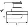
Чертеж
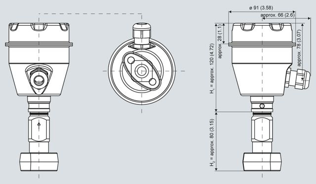
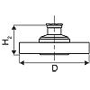
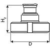
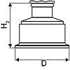
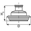
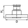
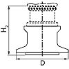
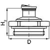
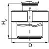
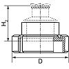
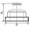
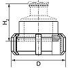
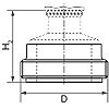
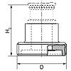
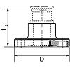
SITRANS P300, with oval flange, dimensions in mm (inch)
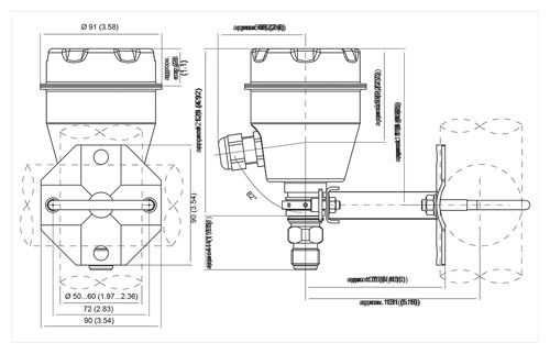
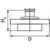
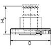
SITRANS P300, process connection M20 x 1.5, with mounted mounting bracket, dimensions in mm (inch)
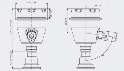
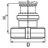
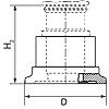
SITRANS P300, flush-mounted, dimensions in mm (inch)
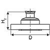
The diagram shows a SITRANS P300 with an example of a flange. In this drawing the height is subdivided into H1 and H2.
H1 = Height of the SITRANS P300 up to a defined cross-section
H2 = Height of the flange up to this defined cross-section
Only the height H2 is indicated in the dimensions of the flanges.
Flanges as per EN and ASME
Flange to EN
EN 1092-1
DN
PN
∅D
H2
25
40
115 mm (4.5")
Approx. 52 mm (2")
25
100
140 mm (5.5")
40
40
150 mm (5.9")
40
100
170 mm (6.7")
50
16
165 mm (6.5")
50
40
165 mm (6.5")
80
16
200 mm (7.9")
80
40
200 mm (7.9")
Flanges to ASME
ASME B16.5
DN
class
∅D
H2
1"
150
110 mm (4.3")
Approx. 52 mm (2")
1"
300
125 mm (4.9")
1½"
150
130 mm (5.1")
1½"
300
155 mm (6.1")
2“
150
150 mm (5.9")
2“
300
165 mm (6.5")
3“
150
190 mm (7.5")
3“
300
210 mm (8.1")
4“
150
230 mm (9.1")
4“
300
255 mm (10.0")
NuG and pharmaceutical connections
Connections to DIN
DIN 11851 (milk pipe union)
DN
PN
∅D
H2
50
25
92 mm (3.6")
Approx. 52 mm (2")
80
25
127 mm (5.0")
TriClamp to DIN 32676
DN
PN
∅D
H2
50
16
64 mm (2.5")
Approx. 52 mm (2")
65
16
91 mm (3.6")
Other connections
Varivent connection
DN
PN
∅D
H2
40 ... 125
40
84 mm (3.3")
Approx. 52 mm (2")
Biocontrol connection
DN
PN
∅D
H2
50
16
90 mm (3.5")
Approx. 52 mm (2")
65
16
120 mm (4.7")
Sanitary process connection to DRD
DN
PN
∅D
H2
50
40
105 mm (4.1")
Approx. 52 mm (2")
Sanitary process screw connection to NEUMO Bio-Connect
DN
PN
∅D
H2
50
16
82 mm (3.2")
Approx. 52 mm (2")
65
16
105 mm (4.1")
80
16
115 mm (4.5")
100
16
145 mm (5.7")
2”
16
82 mm (3.2")
2½”
16
105 mm (4.1")
3”
16
105 mm (4.1")
4”
16
145 mm (5.7")
Sanitary process connection to NEUMO Bio-Connect flange connection
DN
PN
∅D
H2
50
16
110 mm (4.3")
Approx. 52 mm (2")
65
16
140 mm (5.5")
80
16
150 mm (5.9")
100
16
175 mm (6.9")
2”
16
100 mm (3.9")
2½”
16
110 mm (4.3")
3”
16
140 mm (5.5")
4”
16
175 mm (6.9")
Sanitary process connection to NEUMO Bio-Connect clamp connection

DN
PN
∅D
H2
50
16
77.4 mm (3.0")
Approx. 52 mm (2")
65
10
90.9 mm (3.6")
80
10
106 mm (4.2")
100
10
119 mm (4.7")
2”
16
64 mm (2.5")
2½”
16
77.4 mm (3.0")
3”
10
90.9 mm (3.6")
4”
10
779 mm (4.7")
Sanitary process connection to NEUMO Bio-Connect S flange connection
DN
PN
∅D
H2
50
16
125 mm (4.9")
Approx. 52 mm (2")
65
10
145 mm (5.7")
80
10
155 mm (6.1")
100
10
180 mm (7.1")
2”
16
125 mm (4.9")
2½”
10
135 mm (5.3")
3”
10
145 mm (5.7")
4”
10
180 mm (7.1")
Threaded connection G¾", G1" and G2" acc. to DIN 3852
DN
PN
∅D
H2
¾“
63
37 mm (1.5")
Approx. 45 mm (1.8")
1“
63
48 mm (1.9")
Approx. 47 mm (1.9")
2“
63
78 mm (3.1")
Approx. 52 mm (2")
Tank connection TG 52/50 and TG52/150
DN
PN
∅D
H2
25
40
63 mm (2.5")
Approx. 63 mm (2.5")
25
40
63 mm (2.5")
Approx. 170 mm (6.7")
SMS socket with union nut
DN
PN
∅D
H2
2“
25
84 mm (3.3")
Approx. 52 mm (2.1")
2½“
25
100 mm (3.9")
3“
25
114 mm (4.5")
SMS threaded socket
DN
PN
∅D
H2
2“
25
70 x 1/6 mm
Approx. 52 mm (2.1")
2½“
25
85 x 1/6 mm
3“
25
98 x 1/6 mm
IDF socket with union nut
DN
PN
∅D
H2
2“
25
77 mm (3")
Approx. 52 mm (2.1")
2½“
25
91 mm (3.6")
3“
25
106 mm (4.2")
IDF threaded socket
DN
PN
∅D
H2
2“
25
64 mm (2.5")
Approx. 52 mm (2.1")
2½“
25
77,5 mm (3.1")
3“
25
91 mm (3.6")
Aseptic threaded socket to DIN 11864-1 Form A
DN
PN
∅D
H2
50
25
Approx. 52 mm (2.1")
65
25
80
25
100
25
Aseptic flange with notch to DIN 11864-2 Form A
DN
PN
∅D
H2
50
16
Approx. 52 mm (2.1")
65
16
80
16
100
16
Aseptic flange with groove to DIN 11864-2 Form A
DN
PN
∅D
H2
50
16
Approx. 52 mm (2.1")
65
16
80
16
100
Aseptic clamp with groove to DIN 11864-3 Form A
DN
PN
∅D
H2
50
25
Approx. 52 mm (2.1")
65
25
80
16
100
16
Особенности
- High quality and service life
- High reliability even under extreme chemical and mechanical loads
- Extensive diagnosis and simulation functions
- Minimum conformity error
- Small long-term drift
- Wetted parts made of high-grade materials (such as stainless steel, Hastelloy, tantalum)
- Measuring range 0.008 bar to 400 bar (0.1 psi to 5802 psi)
- High measuring accuracy
- Parameterization over control keys and HART communication or PROFIBUS PA communication
Технические данные
SITRANS P300 for gauge and absolute pressure
HART
PROFIBUS PA and FOUNDATION fieldbus
Gauge pressure input
Measured variable
Gauge pressure (flush-mounted)
Spans (infinitely adjustable) or nominal measuring range and
max. permissible test pressureMeasuring span
Max. perm. test pressure
Nominal measuring range
Max. perm. test pressure
0.01 ... 1 bar g
(0.15 ... 14.5 psi g)6 bar g
(87 psi g)1 bar g
(14.5 psi g)6 bar g
(87 psi g)0.04 ... 4 bar g
(0.58 ... 58 psi g)10 bar g
(145 psi g)4 bar g
(58 psi g)10 bar g
(145 psi g)0.16 ... 16 bar g
(2.3 ... 232 psi g)32 bar g
(464 psi g)16 bar g
(232 psi g)32 bar g
(464 psi g)0.6 ... 63 bar g
(9.1 ... 914 psi g)100 bar g
(1450 psi g)63 bar g
(914 psi g)100 bar g
(1450 psi g)1.6 ... 160 bar g
(23.2 ... 2321 psi g)250 bar g
(3626 psi g)160 bar g
(2321 psi g)250 bar g
(3626 psi g)4.0 ... 400 bar g
(58 ... 5802 psi g)500 bar g
(7252 psi g)400 bar g
(5802 psi g)500 bar g
(7252 psi g)Depending on the process connection, the span may differ from these values
Depending on the process connection, the nominal measuring range may differ from these values
Lower measuring limit
- Measuring cell with silicone oil
30 mbar a (0.44 psi a)
Upper measuring limit
- Measuring cell with silicone oil
100 % of max. span
100 % of the max. nominal measuring range
Absolute pressure input
Measured variable
Absolute pressure
Spans (infinitely adjustable) or nominal measuring range and
max. permissible test pressureMeasuring span
Max. perm. test pressure
Nominal measuring range
Max. perm. test pressure
8 ... 250 mbar a
(0.12 ... 3.6 psi a)6 bar a
(87 psi a)250 mbar a
(3.6 psi a)6 bar a
(87 psi a)0.043 ... 1.30 bar a
(0.62 ... 19 psi a)10 bar a
(145 psi a)1.30 bar a
(19 psi a)10 bar a
(145 psi a)0.16 ... 5 bar a
(2.3 ... 73 psi a)30 bar a
(435 psi a)5 bar a
(73 psi a)30 bar a
(435 psi a)1 ... 30 bar a
(14.5 ... 435 psi a)100 bar a
(1450 psi a)30 bar a
(435 psi a)100 bar a
(1450 psi a)Lower measuring limit
- Measuring cell with silicone oil
0 mbar a (0 psi a)
Upper measuring limit
- Measuring cell with silicone oil
100% of max. span
100 % of the max. nominal measuring range
Input of gauge pressure, with flush-mounted diaphragm
Measured variable
Gauge pressure (flush-mounted)
Spans (infinitely adjustable) or nominal measuring range and max. permissible test pressure
Measuring span
Max. perm. test pressure
Nominal measuring range
Max. perm. test pressure
0.01 ... 1 bar g (0.15 ... 14.5 psi g)
6 bar g
(87 psi g)1 bar g
(14.5 psi g)6 bar g
(87 psi g)0.04 ... 4 bar g (0.58 ... 58 psi g)
10 bar g
(145 psi g)4 bar g
(58 psi g)10 bar g
(145 psi g)0.16 ... 16 bar g (2.32 ... 232 psi g)
32 bar g
(464 psi g)16 bar g
(232 psi g)32 bar g
(464 psi g)0.6 ... 63 bar g (9.14 ... 914 psi g)
100 bar g
(1450 psi g)63 bar g
(914 psi g)100 bar g
(1450 psi g)Lower measuring limit
-100 mbar a (-0 psi a)
Upper measuring limit
- Measuring cell with silicone oil
100 % of max. span
100 % of the max. nominal measuring range
Input of absolute pressure, with flush-mounted diaphragm
Measured variable
Absolute pressure (flush-mounted)
Spans (infinitely adjustable) or nominal measuring range and
max. permissible test pressureMeasuring span
Max. perm. test pressure
Nominal measuring range
Max. perm. test pressure
43 ... 1300 mbar a
(0.62 ... 18.9 psi g)10 bar a
(145 psi a)1300 mbar a
(18.9 psi a)10 bar a
(145 psi a)0.16 ... 5 bar a
(2.32 ... 72.5 psi a)30 bar a
(435 psi a)5 bar a
(72.5 psi a)30 bar a
(435 psi a)1 ... 30 bar a
(14.5 ... 435 psi a)100 bar a
(1450 psi a)30 bar a
(435 psi a)100 bar a
(1450 psi a)Depending on the process connection, the span may differ from these values
Depending on the process connection, the nominal measuring range may differ from these values
Lower measuring limit
0 bar a (0 psi a)
Upper measuring limit
- Measuring cell with silicone oil
100% of max. span
100 % of the max. nominal measuring range
Output
Output signal
4 ... 20 mA
Digital PROFIBUS PA signal
Physical bus
-
IEC 61158-2
Protection against polarity reversal
Protected against short-circuit and polarity reversal. Each connection against the other with max. supply voltage.
Electrical damping T63 (step width 0.1 s)
Set to 0.1 s (0 ... 100 s)
Measuring accuracy
Reference conditions
(All error data refer always refer to the set span)Increasing characteristic, start-of-scale value 0 bar, stainless steel seal diaphragm, measuring cell with silicone oil, room temperature 25 °C (77 °F), span ratio (r = max. span / set span)
Measurement deviation with limit setting, including hysteresis and repeatability.
Gauge pressure
Absolute pressure
Absolute pressure, flush-mounted
Gauge pressure
Absolute pressure
Absolute pressure, flush-mounted
Linear characteristic
≤ 0.075 %
≤ 0.01 %
≤ 0.02 %
- r ≤ 10
≤ (0.0029 · r + 0.071)%
≤ 0.1 %
≤ 0.2 %
- 10 < r ≤ 30
≤ (0.0045 · r + 0.071)%
≤ 0.2 %
≤ 0.4 %
- 30 < r ≤ 100
≤ (0.005 · r + 0.05)%
-
-
Settling time T63 without electrical damping
Approx. 0.2 s
Long-term drift at ±30 °C (±54 °F)
≤ (0.25 · r)%/5 years
≤ (0.1 · r)%/year
≤ 0.25 %/5 years
≤ 0.1 %/year
Influence of ambient temperature
- at -10 ... +60 °C (14 ... 140 °F)
≤ (0.08· r + 0.1)%
≤ (0.2 · r + 0.3)%
≤ 0,3 %
≤ 0.5 %
- at -40 ... -10 °C and +60 ... +85 °C
(-40 ... 14 °F and 140 ... 185 °F)
≤ (0.1·r + 0.15) %/10 K
≤ (0.2·r + 0.3) %/10 K
≤ 0.25 %/10 K
≤ 0,5 %/10 K
Influence of the medium temperature (only with flush-mounted diaphragm)
- Temperature difference between medium temperature and ambient temperature
3 mbar/10 K (0.04 psi/10 K)
Rated conditions
Installation conditions
Ambient temperature
Observe the temperature class in areas subject to explosion hazard.
- Measuring cell with silicone oil
-40 ... +85 °C (-40 ... +185 °F)
- Measuring cell with Neobee oil (with flush-mounted diaphragm)
-10 ... +85 °C (14 ... +185 °F)
- Measuring cell with inert liquid (not with flush-mounted diaphragm)
-20 ... +85 °C (-4 ... +185 °F)
- Digital display
-30 ... +85 °C (-22 ... +185 °F)
- Storage temperature
-50 ... +85 °C (-58 ... +185 °F)
(for Neobee: -20 ... +85 °C (-4 ... +185 °F))Climatic class
Condensation
Permissible
Degree of protection acc. to EN 60529
IP65, IP68, NEMA X, enclosure cleaning, resistant to lyes, steam to 150° C (302 °F)
Electromagnetic Compatibility
- Emitted interference and interference immunity
Acc. to EN 61326 and NAMUR NE 21
Medium conditions
Temperature of medium
- Measuring cell with silicone oil
-40 ... +100 °C (-40 ... +212 °F)
- Measuring cell with silicone oil (with flush-mounted diaphragm)
-40 ... +150 °C (-40 ... +302 °F)
- Measuring cell with Neobee oil (with flush-mounted diaphragm)
-10 ... +150 °C (-14 ... +302 °F)
- Measuring cell with silicone oil, with temperature decoupler (only with flush-mounted diaphragm)
-40 ... +200 °C (-40 ... +392 °F)
- Measuring cell with inert liquid
-20 ... +100 °C (-4 ... +212 °F)
- Measuring cell with high-temperature oil
-10 ... +250 °C (14 ... 482 °F)
Design (standard version)
Weight (without options)
Approx. 800 g (1.8 lb)
Enclosure material
Stainless steel, mat. No. 1.4301/304
Material of parts in contact with the medium
- Connection shank
Stainless steel, mat. No. 1.4404/316L or Hastelloy C276, mat. No. 2.4819
- Oval flange
Stainless steel, mat. No. 1.4404/316L
- Seal diaphragm
Stainless steel, mat. No. 1.4404/316L or Hastelloy C276, mat. No. 2.4819
- Measuring cell filling
- Silicone oil
- Inert filling liquid
Process connection
- G½B to EN 837-1
- Female thread ½-14 NPT
- Oval flange PN 160 (MWP 2320 psi) with fastening thread:
- 7⁄16-20 UNF to IEC 61518
- M10 as per DIN 19213
Design (version with flush-mounted diaphragm)
Weight (without options)
Approx. 1 … 13 kg (2.2 … 29 lb)
Enclosure material
Stainless steel, mat. No. 1.4301/304
Material of parts in contact with the medium
- Process connection
Stainless steel, mat. No. 1.4404/316L
- Seal diaphragm
Stainless steel, mat. No. 1.4404/316L
- Measuring cell filling
- Silicone oil
- Inert filling liquid
- FDA compliant fill fluid (Neobee oil)
Process connection
- Flanges as per EN and ASME
- F&B and pharmaceutical flanges
Surface quality touched-by-media
Ra values ≤ 0.8 µm (3.15.10-8 inch)/welded seams Ra ≤ 1.6 µm (6.4.10-8 inch)
(process connections according to 3A; Ra values ≤ 0.8 µm (3.15.10-8 inch)/welded seams Ra ≤ 0.8 µm (3.15.10-8 inch)
Power supply UH
Terminal voltage on transmitter
10.5 ... 42 V DC
for intrinsically safe operation: 10.5 ... 30 V DCSupplied through bus
Separate power supply
-
Not necessary
Bus voltage
- Without EEx
-
9 ... 32 V
- With intrinsically-safe operation
-
9 ... 24 V
Current consumption
- Max. basic current
-
12.5 mA
- Startup current ≤ basic current
-
Yes
- Max. fault current in the event of a fault
-
15.5 mA
Fault disconnection electronics (FDE)
-
Available
Certificates and approvals
Classification according to PED 97/23/EC
For gases of fluid group 1 and liquids of fluid group 1; complies with requirements of Article 3, paragraph 3 (sound engineering practice)
Water, waste water
In preparation
Explosion protection
Intrinsic safety "i"
PTB 05 ATEX 2048
- Marking
Ex II 1/2 G EEx ia/ib IIB/IIC T4, T5, T6
- Permissible ambient temperature
- Temperature class T4
-40 ... +85 °C (-40 ... +185 °F)
- Temperature class T5
-40 ... +70 °C (-40 ... +158 °F)
- Temperature class T6
-40 ... +60 °C (-40 ... +140 °F)
- Interface
To certified intrinsically-safe circuits with peak values:
Ui = 30 V, Ii = 100 mA,
Pi = 750 mW, Ri = 300 ΩTo certified intrinsically-safe circuits with peak values:
FISCO supply unit:
Ui = 17.5 V, Ii = 380 mA,
Pi = 5.32 WLinear barrier:
Ui = 24 V, Ii = 250 mA, Pi = 1.2 W
- Effective inner capacitance:
Ci = 6 nF
Ci = 1.1 nF
- Effective internal inductance:
Li = 0.4 mH
Li ≤ 7 μH
Explosion protection to FM for USA and Canada (cFMUS)
- Identification (DIP) or (IS); (NI)
Certificate of Compliance 3025099
CL I, DIV 1, GP ABCD T4 ... T6; CL II, DIV 1, GP EFG; CL III; CL I, ZN 0/1 AEx ia IIC T4 ... T6; CL I, DIV 2, GP ABCD T4 ... T6; CL II, DIV 2, GP FG; CL III
- Identification (DIP) or (IS)
Certificate of Compliance 3025099C
CL I, DIV 1, GP ABCD T4 ... T6; CL II, DIV 1, GP EFG; CL III; Ex ia IIC 4 ... T6; CL I, DIV 2, GP ABCD T4 ... T6; CL II, DIV 2, GP FG; CL III
Dust explosion protection for zone 20/21/22
PTB 05 ATEX 2048
- Marking
Ex II 1D Ex ia D 20 T 120 °C
Ex II 2D Ex ib D 21 T 120 °C
Ex II 3D Ex ib D 21 T 120 °C
- Permissible ambient temperature
- Temperature class T4
-40 ... +85 °C (-40 ... +185 °F) (with mineral glass window only -20 ... +85 °C (-4 ... +185 °F))
- Temperature class T5
-40 ... +85 °C (-40 ... +185 °F) (with mineral glass window only -20 ... +85 °C (-4 ... +185 °F))
- Temperature class T6
-40 ... +85 °C (-40 ... +185 °F) (with mineral glass window only -20 ... +85 °C (-4 ... +185 °F))
- Connection
To certified intrinsically-safe circuits with peak values:
Ui = 30 V, Ii = 100 mA, Pi = 750 mW
To certified intrinsically-safe circuits with peak values:
Ui = 24 V, Ii = 380 mA, Pi = 5.32 mW
- Effective inner capacitance:
Ci = 6 nF
Ci = 5 nF
- Effective internal inductance:
Li = 0.4 μH
Li = 10 μH
Type of protection Ex nA/nL/ic (Zone 2)
PTB 05 ATEX 2048
- Marking
II 2/3 G Ex ic IIB/IIC T4/T5/T6
II 2/3 G Ex nA T4/T5/T6
II 2/3 G Ex nL IIB/IIC T4/T5/T6
- Permissible ambient temperature
- Temperature class T4
-40 ... +85 °C (-40 ... +185 °F) (with mineral glass window only -20 ... +85 °C (-4 ... +185 °F))
- Temperature class T5
-40 ... +70 °C (-40 ... +158 °F) (with mineral glass window only -20 ... +70 °C (-4 ... +158 °F))
- Temperature class T6
-40 ... +60 °C (-40 ... +140 °F) (with mineral glass window only -20 ... +60 °C (-4 ... +140 °F))
- Ex nA connection
To certified intrinsically-safe circuits with peak values:
Um = 45 V
To certified intrinsically-safe circuits with peak values:
Um = 32 V
- Ex ic/nL connection
To certified intrinsically-safe circuits with
peak values:
Ui = 45 V
To certified intrinsically-safe circuits with
peak values:
Ui = 32 V
- Effective inner capacitance:
Ci = 6 nF
Ci = 5 nF
- Effective internal inductance:
Li = 0.4 mH
Li = 20 μH
HART communication
HART communication
230 ... 1100 Ω
Protocol
HART Version 5.x
Software for computer
SIMATIC PDM
PROFIBUS PA communication
Simultaneous communication with master class 2 (max.)
4
The address can be set using
Configuration tool or local operation
(standard setting Address 126)
Cyclic data usage
- Output byte
5 (one measured value) or
10 (two measured values)
- Input byte
0.1 or 2 (totalizer mode and reset function for dosing)
- Internal preprocessing
Device profile
PROFIBUS PA Profile for Process Control Devices Version 3.0, Class B
Function blocks
2
- Analog input
- Adaptation to customer-specific process variables
Linearly rising or falling characteristic
- Electrical damping T63 , adjustable
0 to 100 s
- Simulation function
Input /Output
- Failure function
parameterizable (last good value, substitute value, incorrect value)
- Limit monitoring
Yes, one upper and lower warning limit and one alarm limit respectively
- Register (totalizer)
Can be reset, preset, optional direction of counting, simulation function of register output
- Failure mode
parameterizable (summation with last good value, continuous summation, summation with incorrect value)
- Limit monitoring
One upper and lower warning limit and one alarm limit respectively
- Physical block
1
Transducer blocks
2
- Pressure transducer block
- Can be calibrated by applying two pressures
Yes
- Monitoring of sensor limits
Yes
- Specification of a container characteristic with
Max. 30 nodes
- Simulation function for measured pressure value and sensor temperature
Constant value or over parameterizable ramp function
Communication Foundation Fieldbus
Function blocks
3 function blocks analog input, 1 function block PID
- Analog input
- Adaptation to customer-specific process variables
Yes, linearly rising or falling characteristic
- Electrical damping T63 , adjustable
0 to 100 s
- Simulation function
Output/input (can be locked within the device with a bridge)
- Failure mode
parameterizable (last good value, substitute value, incorrect value)
- Limit monitoring
Yes, one upper and lower warning limit and one alarm limit respectively
- Square-rooted characteristic for flow measurement
Yes
- PID
Standard FF function block
- Physical block
1 resource block
Transducer blocks
1 transducer block Pressure with calibration, 1 transducer block LCD
- Pressure transducer block
- Can be calibrated by applying two pressures
Yes
- Monitoring of sensor limits
Yes
- Simulation function: Measured pressure value, sensor temperature and electronics temperature
Constant value or over parameterizable ramp function