
- Каталог оборудования Siemens
- Каталог продуктов Siemens Industry
- Приводная техника
- Техника автоматизации
- Системы автоматизации
- Системы визуализации SIMATIC HMI
- Системы идентификации
- Промышленные коммуникации SIMATIC NET
- Промышленные аппараты управления SIRIUS
- Промышленные информационные технологии
- Управление на базе РС
- Системы управления процессом
- Контрольно-измерительные приборы
- Измерительные преобразователи для давления
- Приборы измерения температуры SITRANS T
- Расходомеры
- Уровнемеры
- Позиционеры
- Устройство для защиты и пуска двигателей SIMOCODE-DP
- Сигнализаторы сбоев в промышленном процессе
- Аппаратные ПИД-регуляторы SIPART
- Встраиваемые самописцы и индикаторы
- Технологии взвешивания
- Дополнительные компоненты
- Коммуникации и программное обеспечение
- Directives
- Анализаторы процесса
- Блоки питания SITOP
- Продукты для специальных требований
- Energy
- Автоматизация и безопасность зданий
- Низковольтная коммутационная техника
- Технология безопасности
- Системные решения и продукты для отраслей
- Сервис
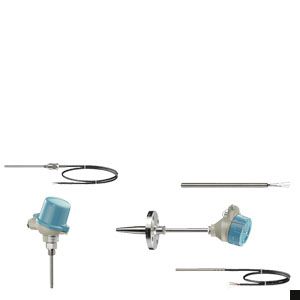
Detailed product overview
- Информационные материалы
Информационные материалы
Type
TS measuring inserts
TS100
TS200
Description
Measuring insert
Temperature sensors in cable version
Temperature sensors in compact version
Application
replaceable
universal use
Version
Mineral-insulated version
Basic version,
Version
Mineral-insulated version
type
in European or
American type
For unfavorable space conditions
Image
Order
Nr. 7MC7010*
7MC7101*
7MC7102*
7MC72*
Material, in contact with media
"1.4571(WtH); 2.4816 (TE)
(316L; Inconnel600Ò)"1.4571
(316TI)
"1.4571(WtH); 2.4816 (TE)
(316L; Inconnel600Ò)"Protective tube types
order separately
without/with separate protective tube
Process connections
-
Compression joints
- Soldering nipple:
- G ¼, G ½
- ½ NPT
- M 8x1, M18x1.5
- Surface connection piece for installation on surfaces/pipes"
Sensor elements
PT100 + thermocouples
Sensor connection
- 1x4 wire
- 2x3 wire
Sensor accuracy
- Class AA
- Class A
- Class B
- Class 1
- Class 2
Connection heads
Type B (Type A pressure resistant)
- Cable, optional with misc. plugs
- misc. plugs
Explosion protection, Europe
II 1 GD Ex ia/ib
II 1 GD Ex d
II 1 GD Ex ia/ib
Output signal
Sensor signal:
- -4 ... 20 mA (TH100/TH200)
- HART (TH300)
- PA (TH400)
- FF (TH400)
Sensor signal
Application
Spare parts
- Mechanical engineering
- Storage temperature
- Surfaces
Limit temperatures1)
- PT100 basis: -30 ... +400 °C
- PT100 extension: -196 ... +600 °C
- Thermocouple: -196 +1100 °C (depending on type)
max. nominal pressure1)
(static pressure at 20°C)"
-
Compression joint max. 40 bar
min. response time t0.5
1.6 … 3.4 s
- 3 mm: 0.35 … 1 s
- 6 mm:1.6 … 3.4 s
Degree of protection
IP54
IP67
1) Load combinations (temperature, flow, vibration, pressure) can at times significantly restrict these values. Other temperature limits result from e.g. protective tube materials with lower limit values (e.g. 1.4571 pressure resilient, 450 ...) 550 °C, limit temperature 800 °C).
Type
TS500 for installation
TS500 Type 2
TS500 Type 2N
Description
Temperature sensors for the process industry (piping and tanks)
Temperature sensors for the process industry (piping and tanks)
Temperature sensors for the process industry (piping and tanks)
Application
Temperature sensors for the installation of existing protective sleeves
Pipe version for minimal to medium stress
Version
suitable for protective sleeves as per DIN 43772 as well as ASME B40.9-2001
Protective tube as per DIN43722, Type 2 without process connection
Protective tube Type 2N similar to DIN 43772, screwed in
type
with extension
- European type
- American type
- without extension, plug-in
- Use with moveable compression joints
without extension, for process temperatures up to 100°C
Image
Order
Nr. 7MC750*
7MC751*-0*(A/B)**-0***
7MC751*-1****-0***
Material, in contact with media
1.4571(WtH); 2.4816 (TE) (316L; Inconnel600Ò)
1.4404; 1.4571 (316L; 316TI)
1.4404; 1.4571 (316L; 316TI)
Protective tube types
order separately
Form 2
Form 2N (similar to Form 2)
Process connections
Connection to protective tube:
- M18x1.5
- G ½
- ½ NPT
Compression joints
- G ½
- ½ NPT
- G ½
- ½ NPT
Mounting length
- 110 mm 2.5 inch 15 inch
- 140 mm 4 inch 18 inch
- 200 mm 6 inch 24 inch
- 260 mm 9 inch
- 410 mm 12 inch
- 160 mm
- 250 mm
- 400 mm
- 100 mm
- 160 mm
- 230 mm
- 360 mm
- 510 mm
Neck tube length
to DIN 43772
non-alignable X=20 mm
Sensor elements
PT100 + thermocouples
Sensor connection
- 1x4 wire
- 2x3 wire
Sensor accuracy
- Class AA
- Class A
- Class B
- Class 1
- Class 2
Connection heads
Type B (Type A pressure resistant)
Explosion protection, Europe
- II 1 GD Ex ia/ib
- II 1 GD Ex d
Output signal
Sensor signal:
- -4 ... 20 mA (TH100/TH200)
- HART (TH300)
- PA (TH400)
- FF (TH400)
Sensor signal
Application
Pipelines and tanks
Limit temperatures1)
- PT100 basis: -30 ... +400 °C
- PT100 extension: -196 ... +600 °C
- Thermocouple: -196 ... +1100 °C (depending on type)
max. nominal pressure1)
(static pressure at 20°C)"
s. protective tube
Pipe Ø 9 mm:
- 0 ... 150 mm 50 bar
- 150 ... 300 mm 40 bar
- Compression joint 20 bar
Pipe Ø 12 mm:
- 0 ... 150 mm 75 bar
- 150 ... 300 mm 60 bar
- Compression joint 10 bar
Pipe Ø 9 mm:
- 0 ... 150 mm 50 bar
- 150 ... 300 mm 40 bar
min. response time t0.5
s. protective tube
19.4 … 29.3 s
Degree of protection
IP65/IP67 (with permissible screwed gland)
1) Load combinations (temperature, flow, vibration, pressure) can at times significantly restrict these values. Other temperature limits result from e.g. protective tube materials with lower limit values (e.g. 1.4571 pressure resilient, 450 ...) 550 °C, limit temperature 800 °C).
Type
TS500 Type 2G
TS500 Type 2F
TS500 Type 3
Description
Temperature sensors for the process industry (piping and tanks)
Temperature sensors for the process industry (piping and tanks)
quicker than Form 2
Application
Pipe version for minimal to medium stress
Version
Protective tube as per DIN 43722, Type 2G, screwed in
Protective tube as per DIN 43722, Type 2F with flange
Protective tube as per DIN 43722, Type 3 without process connection, improved response time
type
- with extension
- without extension, plug-in
- Use with moveable compression joints
Image
Order
7MC751*-1*(A/B)**-1***
7MC751*-2*(A/B)**-1***
7MC751*-0*K**-0***
Material, in contact with media
1.4404; 1.4571 (316L; 316TI)
Protective tube types
Form 2G
Form 2F
Form 3
Process connections
Screw sockets, welded on:
- G 1
- G ½
- ½ NPT
Compression joints
- G ½
- ½ NPT
- G ½
- ½ NPT
Mounting length
- 110 mm 2.5 inch 15 inch
- 140 mm 4 inch 18 inch
- 200 mm 6 inch 24 inch
- 260 mm 9 inch
- 410 mm 12 inch
- 160 mm
- 250 mm
- 400 mm
- 100 mm
- 160 mm
- 230 mm
- 360 mm
- 510 mm
Neck tube length
to DIN 43772
non-alignable X=20 mm
Sensor elements
PT100 + thermocouples
Sensor connection
- 1x4 wire
- 2x3 wire
Sensor accuracy
- Class AA
- Class A
- Class B
- Class 1
- Class 2
Connection heads
Type B (Type A pressure resistant)
Explosion protection, Europe
- II 1 GD Ex ia/ib
- II 1 GD Ex d
Output signal
Sensor signal:
- -4 ... 20 mA (TH100/TH200)
- HART (TH300)
- PA (TH400)
- FF (TH400)
Application
Pipelines and tanks
Limit temperatures1)
- PT100 basis: -30 ... +400 °C
- PT100 extension: -196 ... +600 °C
- Thermocouple: -196 ... +1100 °C (depends on type)
max. nominal pressure1)
(static pressure at 20°C)"
Pipe Ø 9 mm:
- 0 ... 150 mm 50 bar
- 150 ... 300 mm 40 bar
- Compression joint 18 bar
Pipe Ø 12 mm:
- 0 ... 150 mm 75 bar
- 150 ... 300 mm 60 bar
Pipe Ø 9 mm:
- 0 ... 150 mm 50 bar
- 150 ... 300 mm 40 bar
Pipe Ø 12 mm:
- 0 ... 150 mm 75 bar
- 150 ... 300 mm 60 bar
Note restriction imposed by PN of the flange
Pipe Ø 9 mm:
- 0 ... 150 mm 50 bar
- 150 ... 300 mm 40 bar
- Compression joint 10 bar
min. response time t0.5
19.4 … 29.3 s
6.8 … 9.7 s
Degree of protection
IP65/IP67 (with permissible screwed gland)
1) Load combinations (temperature, flow, vibration, pressure) can at times significantly restrict these values. Other temperature limits result from e.g. protective tube materials with lower limit values (e.g. 1.4571 pressure resilient, 450 ...) 550 °C, limit temperature 800 °C).
Type
TS500 Type 3G
TS500 Type 3F
TS500 Type 4/4F
Description
Temperature sensors for the process industry (piping and tanks)
quicker than Form 2
Temperature sensors for the process industry (piping and tanks)
Application
Pipe version for minimal to medium stress
Version
Protective tube as per DIN 43722, Type 3G, screwed in
Protective tube as per DIN 43722, Type 3F with flange
Protective tube to DIN 43722:
- Type 4 for welding
- Type 4F with flange
type
with extension
Image
Order
7MC751*-1*K**-1***
7MC751*-2*K**-1***
7MC752*
Material, in contact with media
1.4404; 1.4571 (316L; 316TI)
Form 4F:
1.4404; 1.4571 (316L; 316TI)
Form 4 additionally:
1.7335; 1.5415(A 182 F11; A 204 Size A)
Protective tube types
Form 3G
Form 3F
- Form 4
- Form 4F
Process connections
Screw sockets, welded on:
- G 1
- G ½
- ½ NPT
Welded flange
- DN 25, PN 40
- 1RF150
- 1.5RF150
- 1.5RF300
For 4 for welding in,
Form 4F with flange:- DN 25, PN 40
- 1RF150
- 1RF300
- 1.5RF150
- 1.5RF300
Mounting length
- 160 mm
- 220 mm
- 280 mm
- 225 mm
- 285 mm
- 345 mm
Form 4F:
as per customer specification
Form 4:
- 110 mm quick
- 140 mm quick/normal
- 200 mm quick/normal
- 260 mm Standard
Neck tube length
to DIN 43772
Sensor elements
PT100 + thermocouples
Sensor connection
- 1x4 wire
- 2x3 wire
Sensor accuracy
- Class AA
- Class A
- Class B
- Class 1
- Class 2
Connection heads
Type B (Type A pressure resistant)
Explosion protection, Europe
II 1 GD Ex ia/ib
II 1 GD Ex d
Output signal
Sensor signal:
- -4 ... 20 mA (TH100/TH200)
- HART (TH300)
- PA (TH400)
FF (TH400)
Application
Pipelines and tanks
Limit temperatures1)
- PT100 -Basis: -30 ... +400 °C
- PT100 extension: -196 ... +600 °C
- Thermocouple: -196 ... +1100 °C (depending on type)
max. nominal pressure1)
(static pressure at 20°C)"
Pipe Ø 12 mm:
- 0 ... 200 mm 75 bar
- 200 ... 300 mm 60 bar
Pipe Ø 12 mm:
- 0 ... 200 mm 75 bar
- 200 ... 300 mm 60 bar
Note restriction imposed by PN of the flange
Mat. (1.4404; 1.4571) :
- 65 mm 450 bar
- 125 mm 350 bar
- Mat. (1.7335; 1.5415) :
- 65 mm 500 bar
- 125 mm 400 bar
Form 4F:
Note restriction imposed by PN of the flange
min. response time t0.5
6.8 … 9.7 s
∅ 18 mm: 12 … 19.7 s
∅ 24 mm: 21.7 … 26.3 s
Degree of protection
IP65/IP67 (with permissible screwed gland)
1) Load combinations (temperature, flow, vibration, pressure) can at times significantly restrict these values. Other temperature limits result from e.g. protective tube materials with lower limit values (e.g. 1.4571 pressure resilient, 450 ...) 550 °C, limit temperature 800 °C).
- Soldering nipple: