
- Каталог оборудования Siemens
- Каталог продуктов Siemens Industry
- Приводная техника
- Техника автоматизации
- Системы автоматизации
- Системы визуализации SIMATIC HMI
- Системы идентификации
- Промышленные коммуникации SIMATIC NET
- Промышленные аппараты управления SIRIUS
- Промышленные информационные технологии
- Управление на базе РС
- Системы управления процессом
- Контрольно-измерительные приборы
- Анализаторы процесса
- Блоки питания SITOP
- Продукты для специальных требований
- Energy
- Автоматизация и безопасность зданий
- Низковольтная коммутационная техника
- Технология безопасности
- Системные решения и продукты для отраслей
- Сервис
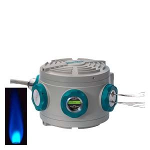
SITRANS CV
- Заказные данные (2)
- Аксессуары (1)
- Информационные материалы
Информационные материалы
The SITRANS CV gas chromatograph (GC), which is based on the innovative analytical technology of the MicroSAM, is an analyzer that has been specially developed for natural gas analysis. The device concept enables the higher and lower calorific value, standard density and Wobbe index (according to ISO, AGA 8, Gost standard) to be determined in a way that is not only cost-effective, but also quick, precise and reliable.
Область применения
- Analysis of natural gas in power plants:
- For quality control
- For turbine optimization
- Pipeline monitoring
- Analysis of natural gas when opening up sea beds (off-shore plants).
- Analysis of bio-natural gas in preprocessing plants
- Analysis of natural gas in liquefaction and regasification plants (LNG Regasification and Storage)
- Determination of calorific value in natural gas for power plants, in gas transfer stations, or during turbine optimization
- Analysis of calorific value in natural gas preparation plants
Дизайн
Enclosure
- Ex d version standard
- Heating adjustable from 60 to 165 °C (isothermal)
- Decentralized installation close to sampling point
Analytical modules
The compact analytical modules contain all the functional components of a chromatograph. The SITRANS CV operates with:
- Live injection
- Valveless live switching on microchip basis
- Standardized analytical modules
- Multidetection through use of up to 8 micro thermal conductivity detectors in smallest possible areas (e.g. on all column/purging outputs and injection)
Функции
Live injection
The SITRANS CV has a two-stage injection system. Using a micro injection valve, a defined quantity of sample is first brought up to the carrier gas pressure. This eliminates the pressure-dependent error in the dosing quantity present with conventional systems. In the second stage, the sample is transferred to the column by a valveless micro injection system (live dosing). The result is an "active" injection.
The injection volume can be varied time-controlled, and exactly matched to the column requirements.
Valveless live column switching
Because of the high dead volume of conventional valves, only the valveless version can be considered for a miniaturized system. In this case, the generation of differences in flow using several electronic pressure regulators at appropriate positions of the column setup causes a change in the flow directions. (The system operates according to the Wheatstone principle, but pneumatically.) The functions "Cut" and "Backflushing" can then be implemented free of dead volume.
The column system
The separation system consists of up to three separation columns connected in series. Micro TCDs or micro live circuits are installed in sequence ("inline") upstream and downstream of the individual columns. Three electronic pressure regulators supply the columns with carrier gas and carry out the switching functions (injection, backflushing and cut).
By using narrow-bore capillary columns, the separation at high resolution is carried out within a much shorter time, approx. factor 2 to 3 compared to standard capillary columns.
Electronic pressure regulators
A high pressure stability together with rapid changing rates in the hPa range are required for precise and fast switching. This is achieved in the electronic pressure regulators by means of a piezo actuator.
Detector
The micro TCDs (silicon wafer technology) work on the principle of continuous measurement of the different thermal conductivities of the carrier gas and the components to be measured.
The measurement can be carried out without falsification by avoiding catalytic effects on the heating wires and maintaining a constant flow velocity. This permits consistent in-line detection, i.e. without qualitative or quantitative losses of substances.
Modules
The standardized application modules generally feature live injection and live switching functions, detectors and separation columns.
Detector
Column 1
Detector
Column 2
Detector
Circuit
Column 3
Detector
C09
Injection
Sil5
Non-polar aromatic and aliphatic hydrocarbons
TCD
Sil5
Non-polar aromatic and aliphatic hydrocarbons
TCD
Live
Porabond Q
All components except molecular filter components
TCD
C01
Injection
TCD
Sil5
C3, C4, C5, C6+
TCD
PoraPLOT/Porabond Q
CO2, C2, H2O
TCD
Live
Molecular filter
H2, (Ar+O2), N2, C1, CO
TCD
C13
Injection
TCD
RTX-1
C3, i-C4, n-C4, neo-C5, i-C5, n-C5
Sum C6+ as sum peak in the backflush
TCD
HayeSepN
N2, CH4, CO2, C2
TCD
Live
Application
The SITRANS CV is a storage product. Precalibration is carried out at the factory, using helium and argon (as the carrier gas) and a calibration gas. The measured components and switching functions (live injection, backflushing, cut) are saved in the GC. The calibration process itself should be performed during commissioning on-site.
Measurements can be made within the following working ranges:
Component
Checked working range (%)
Possible working range (%)
Methane
57 ... 100
50 ... 100
Nitrogen1)
0 ... 22
0 ... 25
Carbon dioxide
0 ... 12
0 ... 20
Ethane
0 ... 14
0 ... 20
Propane
0 ... 5
0 ... 15
i-butane
0 ... 0.9
0 ... 10
n-butane
0 ... 1.8
0 ... 10
Neopentane
0 ... 0.1
0 ... 1
i-pentane
0 ... 0.12
0 ... 1
n-pentane
0 ... 0.12
0 ... 1
Hexane+2)
0 ... 0.08
0 ... 3
Hexane
0 ... 1
Heptane+3)
0 ... 1
Octane
0 ... 1
Nonane+4)
0 ... 1
Helium
Concentration can be entered as a fixed value in the component list
H2S
< 500 ppm
No measured component
High/low calorific value
Calculated
Calculated
Density and relative density
Calculated
Calculated
Wobbe index
Calculated
Calculated
Compressibility factor
Calculated
Calculated
Normalization factor
Calculated
Calculated
Table 1: Measured components and performance parameters for Pos. 8_0 (master setup, standard calorific value analysis in accordance with ISO 6976-1995)
1) Any oxygen or carbon monoxide present in the sample will be detected along with the nitrogen and, therefore, taken into account when the nitrogen concentration is determined.
2) Hexane+ = group(iso/n-hexane to iso/n-nonane)
3) Heptane+ = group(iso/n-hexane) and group(iso/n-heptane to iso/n-nonane)
4) Nonane+ = group(iso/n-hexane), group(iso/n-heptane), group(iso/n-octane), group(iso/n-nonane)
Component
Possible working range (%)
Oxygen
0 ... 4
Table 2: Measuring range of the additional measured component oxygen of the extended calorific value analysis (see article no. 7KQ3105-1)
The remark in footnote 1 about the detection of oxygen and nitrogen is not valid in the case of an extended calorific value analysis. In this case, all components from Table 1 "Measured components and performance parameters for Pos. 8_0 (master setup, standard calorific value analysis in accordance with ISO 6976-1995)" plus oxygen are detected and quantified.
For the analysis of biomethane the following components and their working ranges are measured (Table 3).
Component
Possible working range (%)
Calibration gas for biomethane measurement (%).
Methane
> 80
89
Nitrogen
< 8
4
Ethane
< 6
2.5
Carbon dioxide
< 4
2.5
Propane
< 5
1.0
Butane
< 1.2
0.2
Oxygen
< 3
0.2
2-Methylpropane (isobutane)
< 0.7
0.2
Hydrogen
< 3
0.2
Table 3: Measured components, working ranges and calibration gas for the analysis of biomethane
For analysis of natural gas with backflush summation, the following components and working ranges are measured:
Component
Possible working range (%)
Methane
50 ... 100
Nitrogen
0 ... 25
Carbon dioxide
0 ... 20
Ethane
0 ... 20
Propane
0 ... 15
i-butane
0 ... 10
n-butane
0 ... 10
Neopentane*
i-pentane
0 ... 1
n-pentane
0 ... 1
Hexane+
0 ... 3
Helium
Concentration can be entered as a fixed value in the component list
H2S
No measured component
High/low calorific value
Calculated
Density and relative density
Calculated
Wobbe index
Calculated
Compressibility factor
Calculated
Normalization factor
Calculated
Table 4: Component and measuring ranges for the analysis, including backflush summation
* Because the neopentane concentration is very small in practice, this component is not calibrated and is measured with the relative response factor of isopentane. For this reason, a possible working range is not indicated.
Analyses within the checked working range as well as the quality parameters resulting from these (high and low compression and normalization factors, calorific value, density, relative density and Wobbe index) correspond to the requirements listed below.
Measurements within the scope of the possible working ranges (Table 1 "Measured components and performance parameters for Pos. 8_0 (Master setup, standard analysis of calorific value in accordance with ISO 6976-1995)", right column, and Table 2 "Measuring range of the additional measured component oxygen of the extended analysis of calorific value (see article no. 7KQ3105-1)") are possible. However, checking of the repeatability and correctness has not been carried out by the official German body "Physikalisch technischer Bundesanstalt (PTB)".
Concentration range (mol.%)
Repeatability according to ISO 6974-5 (2001); molar fraction (%), absolute
50 < xi < 100
0.03 ... 0.035
1 < xi < 50
0.011 ... 0.03
0.1 < xi < 1
0.006 ... 0.011
xi < 0.1
< 0.006
Table 5: The repeatability of the measured components complies with ISO 6974-5 (2001) – Annex B (article no. 7KQ3105-0, 7KQ3105-1)
The repeatability of the calorific value and standard density achieve a relative standard deviation of < 0.01%. SITRANS CV for the analysis of biomethane achieves a relative standard deviation of < 0.05%.
The calibration gas is an extremely important factor for consideration in terms of the MPE (maximum permissible error), and has a significant effect on the accuracy of the overall measuring system. For this reason, SITRANS CV - based on a comparative measuring procedure - can never be more accurate than the calibration gas used. Other parameters besides the accuracy data on the calibration gas certificate are important for the accuracy of a system. Examples of these include the optimum gas composition, the ambient temperatures of the calibration gas cylinders during transportation and operation, potential condensation of, for instance, higher hydrocarbons in a calibration gas cylinder, and the functionality of the sample preparation system.
Under optimum conditions, the SITRANS CV achieves an MPE of < 0.1% for the calorific value and the standard density, whereby the system for measuring biomethane produces an MPE of < 0.5%.
SITRANS CV is designed for measuring with various configurations; the calibration gases required for this purpose are shown below. (Table 6, Measurement and calibration gas components):
SITRANS CV – Overview of possible configurations and the required calibration gases
Carrier gas
He
He
Ar
He
Analyzer module
C09
C01
C01
C13
Calorific value analysis C6+
Calorific value analysis C6+ with oxygen
Basic Bio-CH4
Extended calorific value analysis Bio-CH4
C6+ backflush
Calculation standard
Calculation standard is ISO 6976, GOST and AGA 8 can be selected
Article No.
7KQ 3105-0
7KQ 3105-1
7KQ 3105-2
7KQ 3105-2
Hydrogen
-
-
-
M CR
-
Oxygen
-
M CR
M CR
M CR
-
Nitrogen
M CR
M CR
M CR
M CR
M CR
Carbon dioxide
M CR
M CR
M CR
M CR
M CR
Methane
M CR
M CR
M CR
M CR
M CR
Ethane
M CR
M CR
-
M CR
M CR
Propane
M CR
M CR
-
M CR
M CR
Isobutane
M CR
M CR
-
M CR
M CR
Butane
M CR
M CR
-
M CR
M CR
Neopentane
M*1
M*1
-
-
M*1
Isopentane
M CR
M CR
-
-
M CR
Pentane
M CR
M CR
-
-
M CR
Group C6+
M*2 CR
M*2 CR
-
-
-
Group C6+ backflush
-
-
-
-
M*2 CR
Extended application 7KQ 3105- B02
Separate measurement of Group C6 and Group C7+
M*3 CR*3
M*3 CR*3
-
-
-
Separate Groups C6, C7, C8, C9
M*4 CR*4
M*4 CR*4
-
-
-
Caution!
Use of the SITRANS CV with a carrier gas different to that of the supplied solution can lead to faults and to the destruction of the analysis module. Depending on the composition of the calibration gas, external heating for the calibration gas cylinder may be necessary.
M
Measured
CR
Required as calibration component; composition see catalog PA 01 – SITRANS CV - Function
M*1
Neopentane is measured with the response factor of isopentane; for direct calibration of neopentane: see operating instructions
M*2
Group C6+ is measured with the relative response factor of n-hexane
M*3/CR*3
Groups C6 and C7+ are measured separately and calibrated with n-hexane and n-heptane, respectively
M*4/CR*4
Group C6, Group C7, Group C8, Group C9 are measured and calibrated separately
Table 6: Overview of device versions and available measurement configurations and the calibration gas compositions required for them
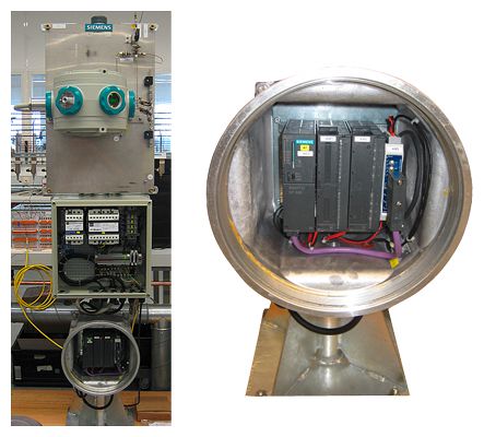
SITRANS CV with SIMATIC Extension Unit
Чертеж
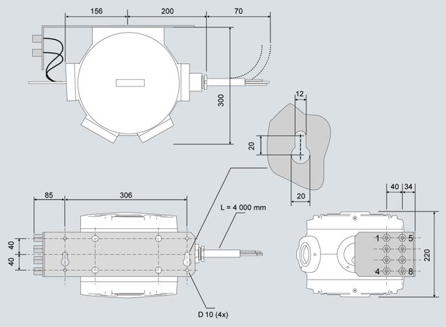
SITRANS CV, dimensions in mm
Особенности
Flexible installation: The rugged and compact design enables installation in even extreme areas of application, such as offshore exploration, or directly at the pipeline. The SITRANS CV has the certification required (such as explosion protection or splashwater protection) to meet the requirements of these applications.
Like the MicroSAM, the SITRANS CV consists of a basic unit and an analysis module, which, if necessary, can be replaced in as short a time as possible. Combined with low power and gas consumption, this keeps operating costs down.
Notable features of the CVControl software, which has been specially developed for calibration-related applications, includes its ease of operation and transparency.
The automatic method optimization integrated in the software increases the repeatability of the calorific value measurement and reduces the cost of ownership.
The serial RS 485/RS 232 and Ethernet interfaces enable communication with both the control system and a flow computer.
Like the MicroSAM, the unit’s high analytical capability can be attributed to narrow-bore capillary columns, live injection, live switching and in-line detection.
Технические данные
Climatic conditions
Permissible ambient temperature
-20 ... +55 °C (depending on oven temperature)
Permissible storage/transport temperature
-30 ... +70 °C
Permissible relative humidity
Max. 90%
Protection against dust and moisture
- According to EN 60529/IEC 60529
IP 65
- According to NEMA 250
NEMA 4X
Power supply
Auxiliary power
24 V DC (18.5 ... 30.2 V)
External fuse
T2.5 A
Power consumption, typical
18 W
Power consumption, maximum
60 W
Dimensions and weights
Width x depth x height
360 x 300 x 220 mm (approx. 14" x 12" x 9")
Weight
15 kg (35 lb.)
Mounting
Installation on
Post, pipe or wall
Distance from wall or next chromatograph
300 mm (12")
Distance from ceiling or floor
200 mm (8")
Electromagnetic compatibility
Noise suppression
According to CISPR 11 / EN 55011 / DIN VDE 0875 Limit class B
EMC immunity
According to IEC 60801/DIN VDE 0843
Conducted interferences on AC supply lines
- According to Part 4 (burst)
2 kV
- According to Part 5 (ms pulses), line against line
1 kV
- According to Part 5 (ms pulses), line against ground
2 kV
Conducted interferences on signal lines
- According to Part 4 (burst)
1 kV
Immunity to static discharge
- According to Part 2 (ESD)
8 kV
Immunity to fields
- According to Part 3 and Part 6
10 V/m
Safety
Electrical safety
IEC 61010 / DIN VDE 0411
Explosion protection
ATEX and IEC Ex: II 2 G Ex d IIC T4 Gb
Class I, Zone 1, Group IIB + H2 T4
Class I, Div 1, Groups B, C, D T4
Factory Sealed
Oven
Number/type
1 / isothermal
Purging with N2
Possible
Dimensions (D x H)
160 x 10 mm
Max. heating power
35 VA
Temperature range
60 … 165 °C
Temperature stability
± 0.1 K (60 ... 165 °C)
Temperature accuracy
± 3 K (60 ... 165 °C)
Retention time variations per 10 °C change in ambient temperature
Approx. 0.3%
Warm-up period from 30 … 100 °C
10 minutes
Columns and gases
Separating column switching
Multidimensional chromatography with backflushing and cut in live system
Multifunctional diaphragm valve
For injection and backflushing
Gas connections
Swagelok 1/8"
Pressure regulators
Max. 4 single-channel electronic pressure regulators
Solenoid valves for control of diaphragm valve
2 NC contacts, 2 NO contacts
Carrier gas
He, Ar
Notice
The carrier gas defined for the delivered state must be used.
Changing the carrier gas could destroy the thermal conductivity detectors.
- Gas purity (minimum requirement)
≥ 99.999 % (5.0)
- Solid components
< 0.1 μm
- Required filtration
Degree of separation 99.99 % for 0.1 μm particles
- Consumption
< 35 ml/min
- Inlet pressure
500 …700 kPa (g)
600 kPa (g) recommended
Important:
A continuous carrier gas supply is required for error-free operation (frequent carrier gas failure has a negative effect on the service life of the detectors and the device-internal pressure regulator). In addition, an external two-layer pressure regulator for the carrier gas pressure is strongly recommended.Instrument air
Not required
Sample and injection
Sample streams
3
Calibration sample streams
1
Phase
Gaseous
Permissible sample pressure
10 … 60 kPa above atmospheric pressure
NOTICE: Sample must not contain ethine (acetylene).Sample flow
20 … 100 ml/min
Max. sample temperature
120°C
Solid components
< 0.1 μm
Required filtration
Degree of separation 99.99 % for 0.1 μm particles
Material with which the sample comes into contact
Stainless steel, fused silica, polyimide
Injection
"Valveless" live injection
- Controller
With multifunctional diaphragm valve
- Injection volume adjustable using switching times
From 2 ... 50 μl
Detectors, calibration and performance data
Detector type
TCD, max. 8 sensors
Cell volume
0.02 µl
Calibration
Manual or automatic, single level
Repeatability for calorific value and density
≤ 0.01% (for natural gas)
Accuracy for calorific value and density
≤ 0.1% (for natural gas)
Linear range
Typically ≥ 104
Cycle time
Application-dependent
Ambient temperature influence
Negligible
Mean Time to Repair/MTBF
< 1 hour / 3 years (without consumables)
Electronics: Communication and analytical controller (CAC)
Microprocessor
Intel 586 architecture
Flash EPROM
128 MB
Dynamic RAM
64 MB
Operating system
Windows CE 5.0
Software
Preinstalled. Modifications or upgrades for operation PC downloadable via network or locally
Electronics: Realtime signal processor (RSP)
Microprocessor
Motorola 68376, 20 MHz
Flash EPROM
1 MB
Static RAM
1 MB
Operating system
Forth
Software
Preinstalled. Modifications or upgrades downloadable via internal service interface
Interfaces
Communication
1 x Ethernet 10BaseT/TCP/IP
Control system coupling
1 x Modbus RS 485/RS 232 RTU/ASCII
Inputs/outputs: Basic equipment
Digital outputs (relay contact 0.4 A/24 V DC)
4, 3 x samples, 1 x calibration
Digital inputs (24 V to optocoupler)
4, for 1 = sample flow; 2 = time synchronization; 3 = revision (results have no effect on average values); 4 = calibration
Status indicator
LEDs
For:
- Supply voltage
- Software Heartbeat
- Ready
- Maintenance request alert
- Fault
- Sample flow
LCD
For:
- Sample stream: S1, S2, S3, S4
- Sample components: e.g. CO2, propane, etc.
- Measured value of sample as numeric value
Recommended operator panel
Personal computer
Desktop or laptop
Processor
At least Pentium III
Clock
≥ 800 MHz
Interfaces
1 x Ethernet
Operating system
Windows XP, Windows 7
Software
CV Control version 1.30.0.0 and higher
Дальнейшая информация
Notes on 7KQ3105-..
Support bracket
For easy mounting, incl. support for 8 gas connections consisting of:
- Mounting part: Dimensions 380 x 110 mm (W x H)
- Bracket for gas connection: Dimensions 146 x 110 mm (D x H), bracket on right side, mounted at right angle
Sample flow switchover
The chromatograph enables automatic selection and switchover of 3 sample flows and 1 calibration flow. The DO signal from the gas chromatograph requires an external relay for the solenoid valve. The sample preparation system can be ordered separately.
Ambient temperatures
Particularly in warmer zones, weather protection is necessary to protect the SITRANS CV against direct solar radiation. The chromatograph is designed as standard for temperatures from -20 to +55 °C. A version in a thermostatically-controlled casing is also available as an option for temperatures outside these limits.
Communication
SITRANS CV has a serial interface (RS 485/RS 232) for MODBUS communication (RTU/ASCII). Modbus mapping can be flexibly used (see manual for more information).
The operator input is by means of another separate interface via Ethernet (TCP/IP).
Other serial and analog (4 to 20 mA) interfaces are optionally possible using an external solution package (see Article No. 7KQ2160).
Documentation
The documentation includes a SITRANS CV Manual and CVControl Operating Manual in English and German. The documents can be found on the enclosed CD. Safety manuals in all EU languages are also available on the CD.
CVControl operating software
The operating software (language: English or Russian) is included in the scope of supply. Windows XP or Windows 7 must be installed on the computer in order to install this software.
Application
A general system check is made of the basic unit and the integrated application module. The module and basic unit are described in the manual. In addition to the standard configuration, additional country-specific and user-specific sub-configurations are available. The performance record ex works contains the analysis check, including a repeatability record (4h test).
The chromatograph is preconfigured; In addition, three CD-ROMS are enclosed:
- SITRANS CV Software (including manuals and CVControl Operating Instructions)
- Country-specific sub-setups
- Parameter backup
Article numbers Pos. 8_0: Applications – Standard calorific value analysis
This application comprises the standard calorific value analysis. The chromatograph's measurement method is set at the factory, using a synthetic natural gas mixture. The performance parameters specified in Table 5 and the criteria explained in the subsequent text apply to the individual components in Table 1 and their physical variables.
The calculation of the calorimetric variables is possible according to the following standards: ISO 6976-95, GOST, AGA 8, where the former is preset. The reference states for the combustion and for the gas volume that must be specified for calculation purposes are preset to the standard state (Tb=25 °C, Tn = 0 °C) and can be easily changed to other reference states during commissioning using the operating software (Tb= operating temperature, Tn= standard temperature).
The CVControl software provides the energy units BTU/ft3, KWh/m3 and MJ/m3.
Article numbers Pos. 8_1: Applications – extended calorific value analysis with oxygen
This position includes the extended calorific value analysis of the components and possible working ranges from Table 1. Oxygen is measured in addition to the listed components (see Table 2).
A carrier gas dry filter (article no. filter set A5E00400116) on the mounting bracket of the SITRANS CV or enclosed separately is used as standard for this measurement.
The remarks concerning oxygen and CO in footnote 1 of Table 1 are no longer applicable to this position. The information concerning calculation and performance parameters are identical to Pos. 8_0.
Important:
For correct operation of SITRANS CV in accordance with Pos. 8_0 and 8_1, all measured components must be present in the calibration gas. The calibration gases listed in the table "Recommended calibration gases for Pos. 8_0 and 8_1" are recommended (also see Table 6):
Component
Pos. 8_0 (mol%)
Pos. 8_1 (mol%)
Oxygen
0.5
Nitrogen
4
4
Carbon dioxide
1.5
1.5
Methane
88.9
88.4
Ethane
4
4
Propane
1
1
Isobutane
0.2
0.2
n-butane
0.2
0.2
Neopentane
0.05
0.05
Isopentane
0.05
0.05
n-pentane
0.05
0.05
n-hexane
0.05
0.05
Table 7: Recommended calibration gases for Pos. 8_0 and 8_1
A summary of the various country-specific setups, i.e. standard settings including measured components and calibration gases, can be found on the parameter backup CD in the "Readme.pdf" document.
Article numbers Pos. 8_2: Applications – Calorific analysis with biomethane
This position contains the analysis of the components and working ranges of the biomethane listed in Table 3. Based on the measured concentrations of the components, the quality parameters – such as heating values – are determined in accordance with the international standards ISO, GOST and AGA analogously to positions 8_0 and 8_1.
Article No. Position 8_3: Applications – Calorific value analysis with backflush summation
This position includes the analysis of the components listed in Table 4, in which case the components starting from C6, including the isomers, are regarded as the sum peak. This variant is especially well suited for natural gases with very low content of higher hydrocarbons, especially C6+.
However, this backflush summation can also be used to effectively analyze natural gas with typical C6+ fractions. The components up to and including C6+ can be analyzed within the possible concentration ranges according to Table 4.
A01 – SITRANS CV for calorific value analysis Position 8_0, 8_1, 8_2 and 8_3 - Russian configuration
This position includes the possibility for ordering SITRANS CV with a Russian Ex certificate.
IMPORTANT: This Russian version results in a change in the nomenclature from SITRANS CV to MicroSAM.
The following also applies to Pos. 8_3: The limits listed in GOST Standard 31371.7-2008 are checked during the inspection and supplied with the device documentation.
B02- SITRANS CV with extended measuring range in combination with Pos. 8_0
This position permits separate measurement of the group isomers of the higher hydrocarbons C6 to C7(+) and C6 to C9 (+). In accordance with the designation C7(+) and C9 (+), a detailed measurement is carried out up to and including n-C9.
Important:
Testing and certification of the SITRANS CV is carried out using the standard calorific value analysis in accordance with Pos. 8_0. If Pos. D02 or D03 has been selected, this does not include repetition of the proof of repeatability (4 h test) of the unit during the factory acceptance.
The following calibration gases are essential for operation of the SITRANS CV including these extended measuring ranges:
Required components
Calibration gas for C6 and C7(+) measurement
(mol%)Calibration gas for C6 and C9(+) measurement
(mol%)Nitrogen
4.00
4.00
Carbon dioxide
1.50
1.50
Methane
89.00
89.00
Ethane
4.00
4.00
Propane
1.00
1.00
Isobutane
0.20
0.20
n-butane
0.20
0.20
Neopentane
0.10
0.10
Isopentane
0.05
0.05
n-pentane
0.05
0.05
n-hexane
0.05
0.05
n-heptane
0.05
0.05
n-octane
0.50
n-nonane
0.50
Table 8: Components and concentrations of the calibration gases for the extended measuring ranges
More detailed information regarding startup of SITRANS CV including C7(+) and C9(+) measurement can be found in the manual and on the enclosed document CD (country-specific setup "Readme.pdf" file)
D01 - Acceptance and customer information - Factory acceptance, visual check, 1 day
The scope of supply is checked and the documentation and operation of the unit explained as part of the factory acceptance process. The factory acceptance does not include repetition of the proof of repeatability (4 h test) of the unit.
D02 - Acceptance and customer information - Factory acceptance with performance record, 1 day
The scope of the tests to be carried out is described in Table 9 "Scope of tests during factory acceptance". When ordering D02, please supplement the desired option from E0x.
Record of component isolation
Through a final check of existing documentation and according to current chromatograms, 5 analyses
Stability test (repeatability)
According to order E01 ... E03
Performance criteria according to Table 3ff.Checking the Modbus connection
Checking or simulation of Modbus communication can be carried out using a flow computer provided by the customer, for example.
Calculation test
Comparison of the values calculated by CVControl with a customer comparison procedure (optional)
Auto-calibration function
Auto-optimization of methodThe two functions are explained theoretically and practically during presentation of CVControl.
Alarm and event messages
Simulation of alarm situations; as per customer requirement
Table 9: Scope of test during factory acceptance
SITRANS CV is a standard product. Only in this manner is it possible to guarantee short delivery times and attractive prices. All performance records required retrospectively require higher overhead. However, will will be happy to come to an agreement regarding implementation.
D03 - Acceptance and customer information - Factory acceptance, each additional day
Only in conjunction with D01 or D02
E0x - Repeatability test
Proof of repeatability over a period of 4 h is included as standard. Longer repeatability records for the unit can be ordered by means of the supplementary item E0x.
E01 to E03 - Repeatability test, 8 h – 24 h – 48 h
Only in conjunction with D02
Linearity tests can be carried out in the factory on request. The standard test gases required for this (Table 10: "Recommended calibration gases for linearity test during acceptance") are provided free of charge. If the customer specifies other calibration gases with different compositions or higher uncertainty requirements, they must provide these gases for acceptance purposes. As an option, Siemens can procure these special calibration gases (subject to a charge).
On request, proof of the complete functionality of the SITRANS CV is possible within the certified temperature and ambient conditions.
Component
Gas #1 (Mol.%)
Gas #2 (Mol.%)
Gas #3 (Mol.%)
Methane
Residual (approximately 75)
Residual (approximately 85)
Residual (approximately 96.5)
Nitrogen
15.5
5
2.5
Carbon dioxide
0.5
2
0.1
Oxygen
0.5
2
4
Ethane
8
4
0.5
Propane
0.5
2
0.15
i-butane
0.15
0.5
0.03
n-butane
0.15
0.5
0.03
Neopentane
0.08
0.3
0.03
i-pentane
0.08
0.3
0.03
n-pentane
0.08
0.3
0.03
Hexane
0.05
0.1
0.015
Table 10: Recommended calibration gases for linearity test during acceptance
The calibration gases have the following uncertainties:
Proportions of component materials (Mol.%)
Uncertainty (or smaller)
0.1 ... 0.25
± 5.00 %
0.25 ... 1
± 1.00 %
1 ... 10
± 0.50 %
10 ... 100
± 0.20 %
Table 11: Uncertainties of calibration gases
Notes on 7KQ2160-..
Analog and serial data transmission
SITRANS CV does not provide internal analog outputs. These properties can be provided by the SIMATIC Extension Unit. This uses the Modbus output of the chromatograph in order to generate up to 8 active analog outputs (standard, more analog outputs on request).
Modbus multiplexers are available in addition, and allow up to 2 Modbus masters to be connected to the SITRANS CV. The distance from the SITRANS CV should not be more than 1 200 m. In the case of an installation without enclosure (without explosion protection), we deliver the components for generation of analog outputs mounted on a rail, otherwise in the Ex d enclosure.
Pos. 08_ 0 - 5 – Analog values via external unit
This position includes:
- Mounting rail
- Power supply
- SIMATIC S 7-300 and SIMATIC S7, Micro Memory Card 3.3 V NFLASH, 64 KB
- Analog output module with terminating connector
- Protocol converter
Pos. 09_ A – C: Modbus multiplexer
(only applicable together with 0-4)
The Modbus signal can be routed using the Modbus multiplexer and connected to two Modbus masters. B specifies supply of the components without CE certificate.
Pos. 10_ A - B: Enclosure
This position includes the option for installation of the SIMATIC extension unit in the hazardous area (Zone 1 and Zone 2). A protective casing Ex d with standard cable glands including the modules required for the analog outputs and the Modbus multiplexer (if applicable) are provided for this purpose.
- Analysis of natural gas in power plants: