
- Каталог оборудования Siemens
- Каталог продуктов Siemens Industry
- Приводная техника
- Техника автоматизации
- Системы автоматизации
- Системы визуализации SIMATIC HMI
- Системы идентификации
- Промышленные коммуникации SIMATIC NET
- Промышленные аппараты управления SIRIUS
- Промышленные информационные технологии
- Управление на базе РС
- Системы управления процессом
- Контрольно-измерительные приборы
- Анализаторы процесса
- Блоки питания SITOP
- Продукты для специальных требований
- Energy
- Автоматизация и безопасность зданий
- Низковольтная коммутационная техника
- Технология безопасности
- Системные решения и продукты для отраслей
- Сервис
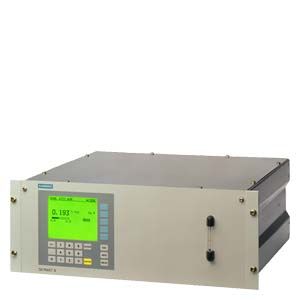
19 unit
- Заказные данные (1)
- Аксессуары (7)
- Информационные материалы
Чертеж
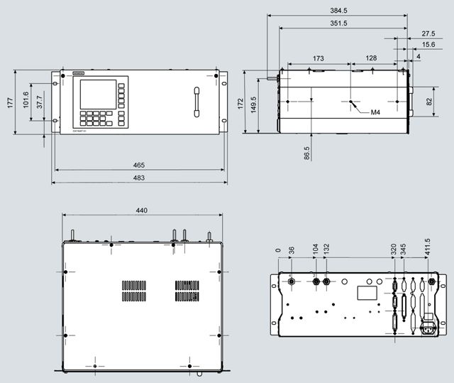
OXYMAT 64, 19" unit, size in mm
Схема подключения
Pin assignment (electrical connections)
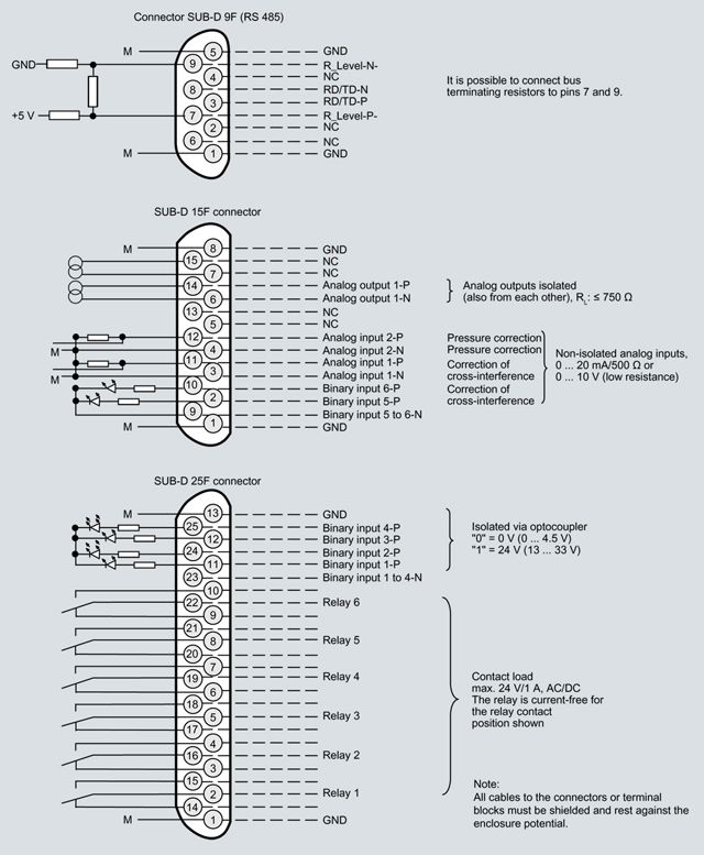
OXYMAT 64, 19" unit, pin assignment
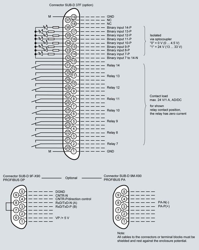
OXYMAT 64, 19" unit, pin assignment of the AUTOCAL plate and PROFIBUS plug
Gas connections and pin assignment
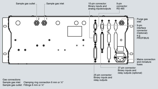
OXYMAT 64, 19" unit, gas connections and electrical connections
Технические данные
General
Measurement ranges
4, internally and externally switchable; automatic measurement range changeover also possible
Smallest possible measuring span (relating to sample gas pressure 1000 hPa absolute, 0.5 l/min sample gas flow and 25 °C ambient temperature)
0 ... 10 vpm O2
Largest possible measuring span
0 ... 99999 vpm
Operating position
Front wall vertical
Conformity
CE mark in accordance with EN 50081-1, EN 50082-2 and RoHS
Design, enclosure
Degree of protection
IP20 according to EN 60529
Weight
Approx. 11 kg
Electrical characteristics
EMC (Electromagnetic Compatibility)
In accordance with standard requirements of NAMUR NE21 (08/98) and EN 61326
Electrical safety
According to EN 61010-1, overvoltage category II
Auxiliary power
100 ... 120 V AC (nominal use range
90 ... 132 V), 48 ... 63 Hz or
200 ... 240 V AC (nominal use range
180 ... 264 V), 48 ... 63 Hz
Power consumption
Approx. 37 VA
Fuse values
100 ... 120 V: 1.0T/250
200 ... 240 V: 0.63T/250
Gas inlet conditions
Sample gas flow
- through the sensor
7.5 l/h
- Overall consumption
15 ... 30 l/h
Permissible sample gas pressure
- without internal pressure regulator
2000 hPa (abs.)
- with internal pressure regulator
2000 ... 6000 hPa (abs.)
Sample gas temperature
0 ... 50 °C
Sample gas humidity
< 1% relative humidity
Dynamic response
Heating time
at room temperature < 30 min (the technical specification is will be observed after 2 hours)
Display delay (T90)
~ 1 min upon switch from N2 to air
Damping (electrical time constant)
0 ... 100 sec, parameterizable
Dead time (purge time of the gas route in the device at 125 ml/min)
10 ... 30 sec
Time for device-internal signal processing
< 1 sec
Pressure correction range
Pressure sensor internal
800 ... 1100 hPa (abs.) (permissible sample gas pressure, see gas inlet conditions)
Measuring behavior (relating to sample gas pressure 1000 hPa absolute, 7.5 l/min sample gas flow and 25 °C ambient temperature)
Output signal fluctuation
< 1 % of the smallest possible measurement range as per nameplate with electronic damping constant of 1 s
Zero point drift
< ± 1% of the current measuring span/month
Measured value drift
< ± 1% of the current measuring span/month
Repeat precision
< 3% of the current measuring span
Minimum detectable quantity
1% of current measurement range,
< 0.1 vpm in measurement range
0 ... 10 vpm
Deviation of linearity
< 2% of the current measuring span
Influencing variables (relating to sample gas pressure 1000 hPa absolute, 7.5 l/min sample gas flow and 25 °C ambient temperature)
Ambient temperature
< 2%/10 K relating to the current measuring span
Sample gas pressure only possible if the sample gas can flow out into the ambient air
When pressure compensation has been switched off: < 1% of the current measuring span/1% pressure change
When pressure compensation has been switched on: < 0.2% of the current measuring span/1% pressure change
Carrier gases, zero point deviation
- Catalytically active sensor (CAZ)
Only gases with non-combustible carrier gas components can be introduced
- Catalytically inactive sensor (CIZ)
Carrier gas concentration of 10 vpm H2; CO and CH4 have a low diagonal effect; higher CVs (concentration values) are negligible
Sample gas flow
< 2% of the smallest possible measuring span with a flow change of 10 ml/min
Auxiliary power
< 0.1% of the current measurement range with nominal voltage ± 10%
Electrical inputs and outputs
Analog output
0/2/4 ... 20 mA, 4 ... 20 mA (NAMUR), potential-free; apparent ohmic resistance max. 750 Ω
Relay outputs
6, with changeover contacts, freely parameterizable, e.g. for measurement range identification; load capacity: 24 V AC/DC / 1 A, potential-free
Analog inputs
2, designed for 0/2/4 ... 20 mA for pressure sensor external and carrier gas inflow correction (diagonal gas correction)
Binary inputs
6, designed for 24 V, potential-free, freely parameterizable, e.g. for measurement range changeover
Serial interface
RS 485
Options
AUTOCAL function each with 8 additional binary inputs and relay outputs, also with PROFIBUS PA or PROFIBUS DP
Climatic conditions
Permissible ambient temperature
-40 ... +70 °C during storage and transportation, 5 ... +45 °C during operation
Permissible humidity
< 90% relative humidity within average annual value, during storage and transportation (no passing below the dew point)