
- Каталог оборудования Siemens
- Каталог продуктов Siemens Industry
- Приводная техника
- Техника автоматизации
- Системы автоматизации
- Системы визуализации SIMATIC HMI
- Системы идентификации
- Промышленные коммуникации SIMATIC NET
- Промышленные аппараты управления SIRIUS
- Промышленные информационные технологии
- Управление на базе РС
- Системы управления процессом
- Контрольно-измерительные приборы
- Анализаторы процесса
- Блоки питания SITOP
- Продукты для специальных требований
- Energy
- Автоматизация и безопасность зданий
- Низковольтная коммутационная техника
- Технология безопасности
- Системные решения и продукты для отраслей
- Сервис
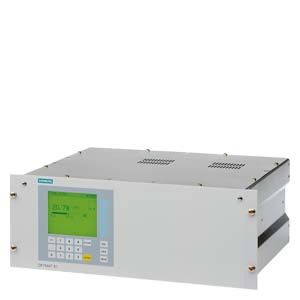
19'' - корпус
- Заказные данные (1)
- Аксессуары (7)
- Информационные материалы
Чертеж
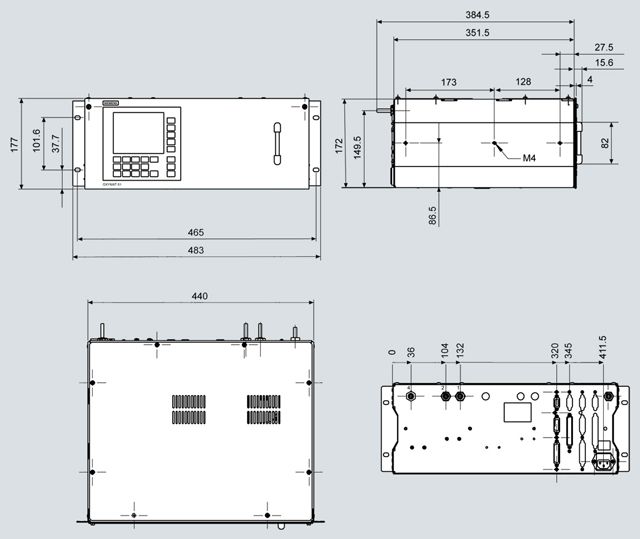
OXYMAT 61, 19“ unit, dimensions in mm
Схема подключения
Pin assignment (electrical connections)
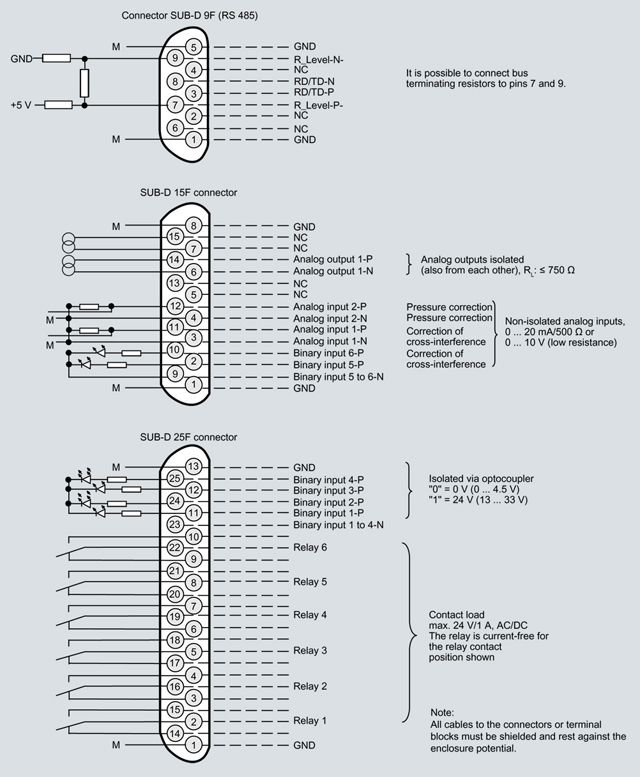
OXYMAT 61, 19“ unit, pin assignment
Pin assignment (electrical connections)
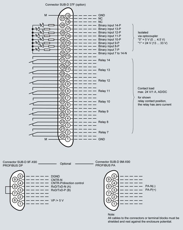
OXYMAT 61, 19“ unit, pin assignment of the Autocal board and PROFIBUS connectors
Gas and electrical connections
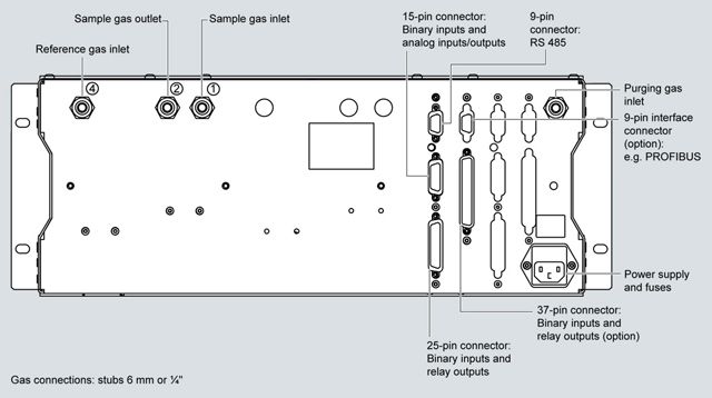
OXYMAT 61, 19“ unit, gas and electrical connections
Технические данные
OXYMAT 61, 19“ unit
General
Measuring ranges
4, switchable internally and externally; autoranging is also possible
Smallest possible measuring span (referred to 1000 hPa absolute sample gas pressure, 0.5 l/min sample gas flow and 25 °C ambient temperature)
2% v/v or 5% v/v O2
Largest possible measuring span
100 % v/v O2
Measuring ranges with suppressed zero
Any zero point is possible between 0 and 100 % v/v as long as a suitable reference gas is used
Position of use
Front panel vertical
Conformity
CE identification EN 50081-1, EN 50082-2
Design, enclosure
Degree of protection
IP20 according to EN 60529
Weight
Approx. 13 kg
Electrical characteristics
Power supply
(see rating plate)100 to 120 V AC (rated range 90 V to 132 V), 48 to 63 Hz or
200 to 240 V AC (rated range 180 V to 264 V), 48 to 63 Hz
Power consumption
Approx. 37 VA
EMC interference immunity (ElectroMagnetic Compatibility)
According to standard requirements of NAMUR NE21 (08/98)
Electrical safety
According to EN 61010-1, overvoltage category III
Fuses
100...120 V: 1.0T/250, 200...240 V: 0.63T/250
Gas inlet conditions
Permissible sample gas pressure
- External reference gas supply
800 … 1200 hPa
- with integrated pump
atmospheric pressure ± 50 hPa
Sample gas flow
18 … 60 l/h (0.3 … 1 l/min)
Sample gas temperature
0 … 50 ºC
Sample gas humidity
< 90% relative humidity
Time response
Warm-up period
With ambient temperature < 30 min
(maximum accuracy achieved after 2 hours)
Response time (T90)
3.5 s
Damping (electric time constant)
0 to 100 s, programmable
Dead time (purging time of gas path in analyzer at 1 l/min)
Approx. 0.5 to 2.5 s, depending on version
Time for internal signal processing
< 1 s
Pressure correction range
Pressure sensor, internal
500 … 2000 hPa absolute (permitted sample gas pressure see gas inlet conditions)
Measuring response (referred to 1000 hPa absolute sample gas pressure, 0.5 l/min sample gas flow and 25 °C ambient temperature)
Output signal fluctuation
< 0.75% of smallest possible measuring range specified on rating plate with an electronic time constant of 1 s (corresponds to ± 0.25% with 2σ)
Zero drift
< 0.5%/month of smallest possible measuring span specified on rating plate
Measured-value drift
< 0.5%/month of respective measuring span
Repeatability
< 1% of respective measuring span
Minimum detectable quantity
1% of current measuring range
Linearity error
< 1% of respective measuring span
Influencing variables (referred to 1000 hPa absolute sample gas pressure, 0.5 l/min sample gas flow and 25 °C ambient temperature)
Ambient temperature
< 0.1% [% O2] /1 K referred to the smallest possible measuring span according to rating plate
Sample gas pressure (with air (approx. 100 hPa) as reference gas, a correction of the atmospheric pressure fluctuations is only possible when the sample gas is vented to ambient air)
Without pressure compensation:
< 2% of measuring span/1% change in pressure;
with pressure compensation:
< 0.2% of measuring span/1% change in pressure
Residual gases
Deviation in zero point corresponding to paramagnetic or diamagnetic deviation of residual gas (see table)
Sample gas flow
< 1% of smallest possible measuring span according to rating plate with a change in flow of 0.1 l/min within the permissible flow range
Power supply
< 0.1% of output signal span with rated voltage ± 10%
Electric inputs and outputs
Analog output
0/2/4 … 20 mA, floating; max. load 750 Ω
Relay outputs
6, with changeover contacts, freely selectable, e.g. for range identification; loading capacity: 24 V AC/DC/ 1 A, floating
Analog inputs
2, designed for 0/2/4 to 20 mA, for external pressure sensor and correction of influence of residual gas (correction of cross interference)
Binary inputs
6, designed for 24 V, floating, freely-selectable, e.g. for range switching
Serial interface
RS 485
Options
Autocal function with 8 binary inputs and 8 relay outputs; also with PROFIBUS PA or PROFIBUS DP
Ambient conditions
Perm. ambient temperature
-30 … +70 °C during storage and transport,
+5 … +45 ºC during operation
Permissible humidity
< 90% relative humidity as annual average, during storage and transport (dew point must not be fallen below)