
- Каталог оборудования Siemens
- Каталог продуктов Siemens Industry
- Приводная техника
- Техника автоматизации
- Системы автоматизации
- Системы визуализации SIMATIC HMI
- Системы идентификации
- Промышленные коммуникации SIMATIC NET
- Промышленные аппараты управления SIRIUS
- Промышленные информационные технологии
- Управление на базе РС
- Системы управления процессом
- Контрольно-измерительные приборы
- Анализаторы процесса
- Блоки питания SITOP
- Продукты для специальных требований
- Energy
- Автоматизация и безопасность зданий
- Низковольтная коммутационная техника
- Технология безопасности
- Системные решения и продукты для отраслей
- Сервис
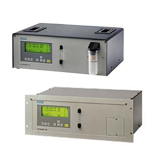
19 rack unit and portable version
- Заказные данные (6)
- Аксессуары (6)
- Информационные материалы
Чертеж
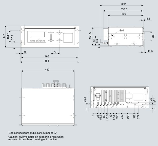
ULTRAMAT 23, 19" rack unit, dimensions in mm
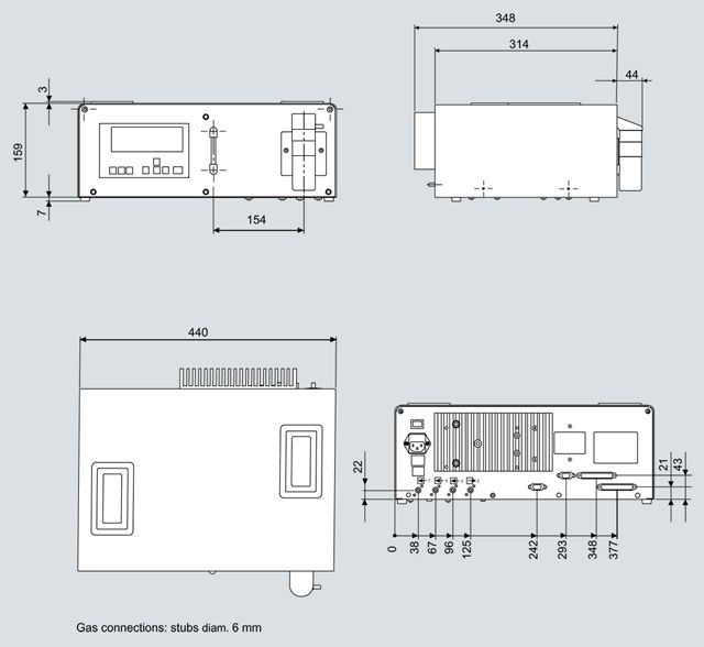
ULTRAMAT 23, bench-top unit, dimensions in mm
Схема подключения
Pin assignment (electrical and gas connections)
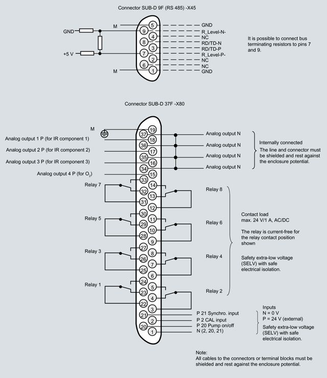
ULTRAMAT 23, pin assignment (standard)
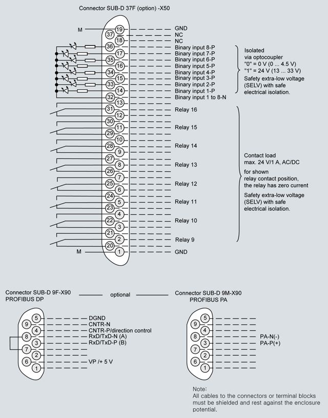
ULTRAMAT 23, pin assignment of optional PROFIBUS interface card
19" rack unit
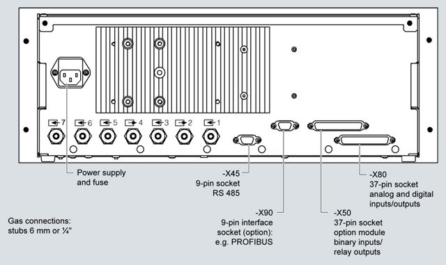
ULTRAMAT 23, 19" rack unit, e.g. an IR measured component with oxygen measurement
Portable unit
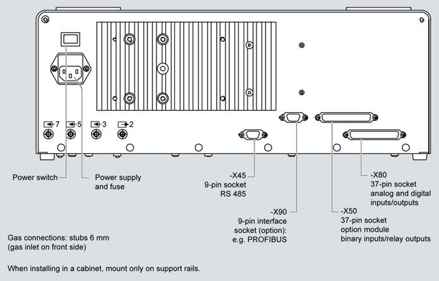
ULTRAMAT 23 portable, in sheet-steel enclosure, gas connections and electrical connections
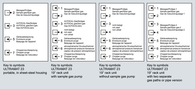
ULTRAMAT 23, designation of the different labels
Технические данные
19" rack unit and portable version
General information
Measured components
Maximum of 4, comprising up to 3 infrared-sensitive gases and oxygen
Measuring ranges
2 per measured component
Display
LCD with LED backlighting and contrast control; function keys; 80 characters (4 lines/20 characters)
Operating position
Front wall, vertical
Conformity
CE symbol EN 61000-6-2, EN 61000-6-4
Design, enclosure
Weight
Approximately 10 kg
Degree of protection, 19" rack unit and desktop model
IP20 according to EN 60529
Electrical characteristics
EMC interference immunity (electromagnetic compatibility)
Safety extra-low voltage (SELV) with safe isolationIn accordance with standard requirements of NAMUR NE21 (08/98) or EN 50081-1, EN 50082-2
Auxiliary power
100 V AC, +10%/-15%, 50 Hz,
120 V AC, +10%/-15%, 50 Hz,
200 V AC, +10%/-15%, 50 Hz,
230 V AC, +10%/-15%, 50 Hz,
100 V AC, +10%/-15%, 60 Hz,
120 V AC, +10%/-15%, 60 Hz,
230 V AC, +10%/-15%, 60 Hz
Power consumption
Approx. 60 VA
Electrical inputs and outputs
Analog output
Per component, 0/2/4 up to 20 mA, NAMUR, isolated, max. load 750 Ω
Relay outputs
8, with changeover contacts, freely parameterizable, e.g. for measuring range identification;
24 V AC/DC/1 A load, potential-free, non-sparking
Digital inputs
3, dimensioned for 24 V, potential-free
- Pump
- AUTOCAL
- Synchronization
Serial interface
RS 485
AUTOCAL function
Automatic unit calibration with ambient air (depending on measured component),
adjustable cycle time from 0 (1) … 24 hoursOptions
Add-on electronics, each with 8 additional digital inputs and relay outputs for e.g. triggering of automatic calibration and for PROFIBUS PA or PROFIBUS DP
Climatic conditions
Permissible ambient temperature
- During operation
5 to 45 °C
- During storage and transportation
-20 ... +60 °C
Permissible ambient humidity
< 90% RH (relative humidity) during storage and transportation
Permissible pressure fluctuations
600 … 1 200 hPa
Gas inlet conditions
Sample gas pressure
- Without pump
Unpressurized (< 1 200 hPa, absolute)
- With pump
Depressurized suction mode, set in factory with 2 m hose at sample gas outlet; full-scale value calibration necessary under different venting conditions
(800 ... 1 050 hPa, absolute)Sample gas flow
72 … 120 l/h (1.2 … 2 l/min)
Sample gas temperature
Min. 0 to max. 50 °C, but above the dew point
Sample gas humidity
< 90% RH (relative humidity), non-condensing
Infrared channel
So that the technical data can be complied with, a cycle time of ≤ 24 hours must be activated for the AUTOCAL. The cycle time of the AUTOCAL function must be ≤ 6 hours when measuring small NO and SO2 measuring ranges (≤ 400 mg/m³) on TÜV/QAL-certified systems.
Measuring ranges
See ordering data
Chopper compartment flushing
Upstream pressure approximately 3 000 hPa; purging gas consumption approximately 100 ml/min
Time response
Warm-up period
Approximately 30 min (at room temperature) (the technical specification will be met after 2 hours)
Delayed display (T90 time)
Dependent on length of analyzer chamber, sample gas line and parameterizable attenuation
Damping (electrical time constant)
Parameterizable from 0 … 99.9 s
Measuring response
Based on sample gas pressure 1 013 hPa absolute, 1.0 l/min sample gas flow and 25 °C ambient temperature
Output signal fluctuation
< ± 1% of the current measuring range (see rating plate)
Detection limit
1% of the current measuring range
Linearity error
- In the largest possible measuring range:
< ± 1% of the measuring range full scale value - In the smallest possible measuring range:
< ± 2% of the measuring range full scale value
Repeatability
≤ ± 1% of the current measuring range
Drift
Zero point
- With AUTOCAL
Negligible
- Without AUTOCAL
< 2 % of the current measuring range/week
Full-scale value drift
- With AUTOCAL
Negligible
- Without AUTOCAL
< 2 % of the current measuring range/week
Influencing variables
Based on sample gas pressure 1 013 hPa absolute, 1.0 l/min sample gas flow and 25 °C ambient temperature
Temperature
Max. 2% of the smallest possible measuring range according to rating plate per 10 K with an AUTOCAL cycle time of 6 h
Atmospheric pressure
< 0.2% of the current measuring range per 1% pressure variation
Auxiliary power
< 0.1% of the current measuring range with a change of ± 10%
Oxygen channel (electrochemical)
Measuring ranges
0 … 5 % … 0 … 25 % O2, parameterizable
Service life
Approx. 2 years with 21 % O2
Detection limit
1% of the current measuring range
Time response
Delayed display (T90 time)
Dependent on dead time and parameterizable attenuation, not > 30 s at approximately 1.2 l/min sample gas flow
Measuring response
Based on sample gas pressure 1 013 hPa absolute, 1.0 l/min sample gas flow and 25 °C ambient temperature
Output signal fluctuation
< ± 0.5% of the current measuring range
Linearity error
< ± 0.2% of the current measuring range
Repeatability
≤ 0.05 % O2
Drift
- With AUTOCAL
Negligible
- Without AUTOCAL
1% O2/year in air, typical
Influencing variables
Based on sample gas pressure 1 013 hPa absolute, 1.0 l/min sample gas flow and 25 °C ambient temperature
Temperature
< ± 0.5% O2 per 20 K, relating to a measured value at 20 °C
Atmospheric pressure
< 0.2% of the measured value per 1% pressure variation
Accompanying gases
The oxygen sensor must not be used if the accompanying gas contains the following components: Chlorine or fluorine compounds, heavy metals, aerosols, mercaptans, alkaline components (such as NH3 in % range)
Typical combustion exhaust gases
Influence: < 0.05% O2
Humidity
H2O dew point ≥ 2 °C; the oxygen sensor must not be used with dry sample gases (however, no condensation either)
H2S channel for measuring ranges of 5 ... 50 vpm
Measured components
Maximum of 4, comprising up to 2 infrared-sensitive gases, an oxygen component and a hydrogen sulfide component
Measuring ranges
- Smallest measuring range
0 ... 5 vpm
- Largest measuring range
0 ... 50 vpm
Service life of the sensor
Approx. 12 months
Permissible atmospheric pressure
750 ... 1 200 hPa
Permissible operating temperature
5 ... 40 °C (41 ... 104 °F)
Operating mode
- Continuous measurement between 0 and 12.5 vpm
- Discontinuous measurement between 12.5 and 50 vpm
Influencing variables
Accompanying gases
The hydrogen sulfide sensor must not be used if the accompanying gas contains the following components:
- Compounds containing chlorine
- Compounds containing fluorine
- Heavy metals
- Aerosols
- Alkaline components
(e.g. NH3 > 5%)
Cross-inferences (interfering gases)
1 360 vpm SO2 result in a cross-interference of < 20 vpm H2S
180 vpm NO result in a cross-interference of < 150 vpm H2S
No cross-interference of CH4, CO2 and H2 (1 000 vpm)
Drift
< 1% of the current measuring range per month
Temperature
< 3% /10 K referred to full-scale value
Atmospheric pressure
< 0.2% of the measured value per 1% pressure variation
Measuring response
Delayed display (T90 time)
< 40 s with sample gas flow of approx. 1 ... 1.2 l/min
Output signal noise
< 2% of smallest measuring range with an attenuation constant of 30 s
Display resolution
< 0.01 vpm H2S
Output signal resolution
< 1% of smallest measuring range with an attenuation constant of 30 s
Repeatability
< 4% of smallest measuring range
Paramagnetic oxygen cell
Measured components
Maximum of 4, comprising up to 3 infrared-sensitive gases and an oxygen component
Measuring ranges
2 per component
- Min. 0 ... 2% vol O2
- Max. 0 ... 100% vol O2
- Suppressed measuring range possible; e.g. 95 ... 100%
Permissible atmospheric pressure
700 ... 1 200 hPa
Permissible operating temperature
5 ... 45 °C (41 ... 113 °F)
Cross-inferences (interfering gases)
See Table "Cross-sensitivities"
Zero point drift
- Measuring range 2%: max. 0.1% with weekly zero adjustment
- Measuring range 5%: max. 0.1% with weekly zero adjustment
- Measuring range 25% or greater:
max. 0.5% with monthly zero adjustment
Measured-value drift
Negligible with AUTOCAL
Temperature error
< 2%/10 K referred to measuring range 5%
< 5%/10 K referred to measuring range 2%
Humidity error for N2 with 90% relative humidity after 30 min
< 0.6% at 50 °C
Atmospheric pressure
< 0.2% of measured value per 1% pressure variation
Delayed display (T90 time)
< 60 s
Output signal noise
< 1% of smallest measuring range
Repeatability
< 1% of smallest measuring range
Дальнейшая информация
Ordering notes
Special selection rules must be observed when measuring some components.
Measured component N2O
7MB2335, 7MB2337 and 7MB2338
(application: Si chip production)- Measuring range 0 to 100 / 500 vpm (MB designation "E")
- Can only be used to measure N2O in ultra-pure gases
7MB2337 and 7MB2338
(application: measurement in accordance with the requirements of the Kyoto protocol)- Measuring range 0 to 500 / 5 000 vpm (MB designation "Y")
- Requires simultaneous measurement of CO2 for correction of cross-interference
7MB2337-*CP*0-*SY* or
7MB2338-*DC*0-*SY* (including NO measurement)7MB2337 and 7MB2338
(application with paramagnetic oxygen measuring cell and separate gas path)7MB2337-4**80-**** - Z + C11
7MB2337-5**80-**** - Z + C117MB2338-4**80-**** - Z + C11
7MB2338-5**80-**** - Z + C11Measured component SF6
7MB2335, 7MB2337 and 7MB2338
(application: SI chip production)- Measuring range 0 to 500 / 2 500 vpm (MB designation "H")
- Can only be used to measure SF6 in inert gases
Calibration interval (MCERTs versions 7MB2335, 7MB2337, 7MB2338)
Component
Smallest measuring range
Calibration interval
Remarks
Z suffix
CO
0 to 150 mg/m³
5 months
IED 2010/75/EC
E50
CO
0 … 250 mg/m³
12 months
IED 2010/75/EC
NO
0 … 100 mg/m³
5 months
IED 2010/75/EC
NO
0 … 250 mg/m³
12 months
IED 2010/75/EC
SO2
0 to 400 mg/m³
12 months
IED 2010/75/EC
N2O
0 … 500 vpm
Kyoto protocol
N2O
0 … 50 mg/m³
6 months
IED 2010/75/EC
Calibration interval (TÜV versions 7MB2355, 7MB2357, 7MB2358)
Component
Smallest measuring range
Calibration interval
Remarks
Z suffix
CO
0 ... 200 mg/m³
1 month
13th/27th BImSchV
T13/T23/T33
NO
0 to 150 mg/m³
1 month
13th/27th BImSchV
T13/T23/T33
SO2
0 to 400 mg/m³
1 month
13th/27th BImSchV
T13/T23/T33
AUTOCAL
(ambient air)AUTOCAL
(inert gas e.g. N2)Calibration with calibration gas
Comment (keep to technical specs)
Zero point
Calibration point
Zero point
Calibration point
Zero point
Calibration point
Hours
Weeks
IR components
3 ... 24
3 ... 24
o
52
O2 - electrical chemical sensor
Stable
3 ... 24
Stable
-
52
o
O2 paramagnetic Cell
-
3 ... 24
x
x
1
o
at MB < 5%
-
3 ... 24
x
x
8
o
at MB > 5%
O2 paramagnetic Cell
x
x
3 ... 24
-
o
52
at MB < 5%
x
x
3 ... 24
-
o
52
at MB > 5%
H2S sensor
3
-
3
-
o
4
o = with AUTOCAL, x = not applicable
Calibration intervals, standard devices